User manual Pomac PLP Lobe pump
CE/PLP (1406) EN-12 9
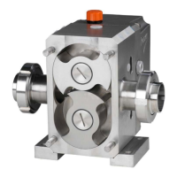
3. General information
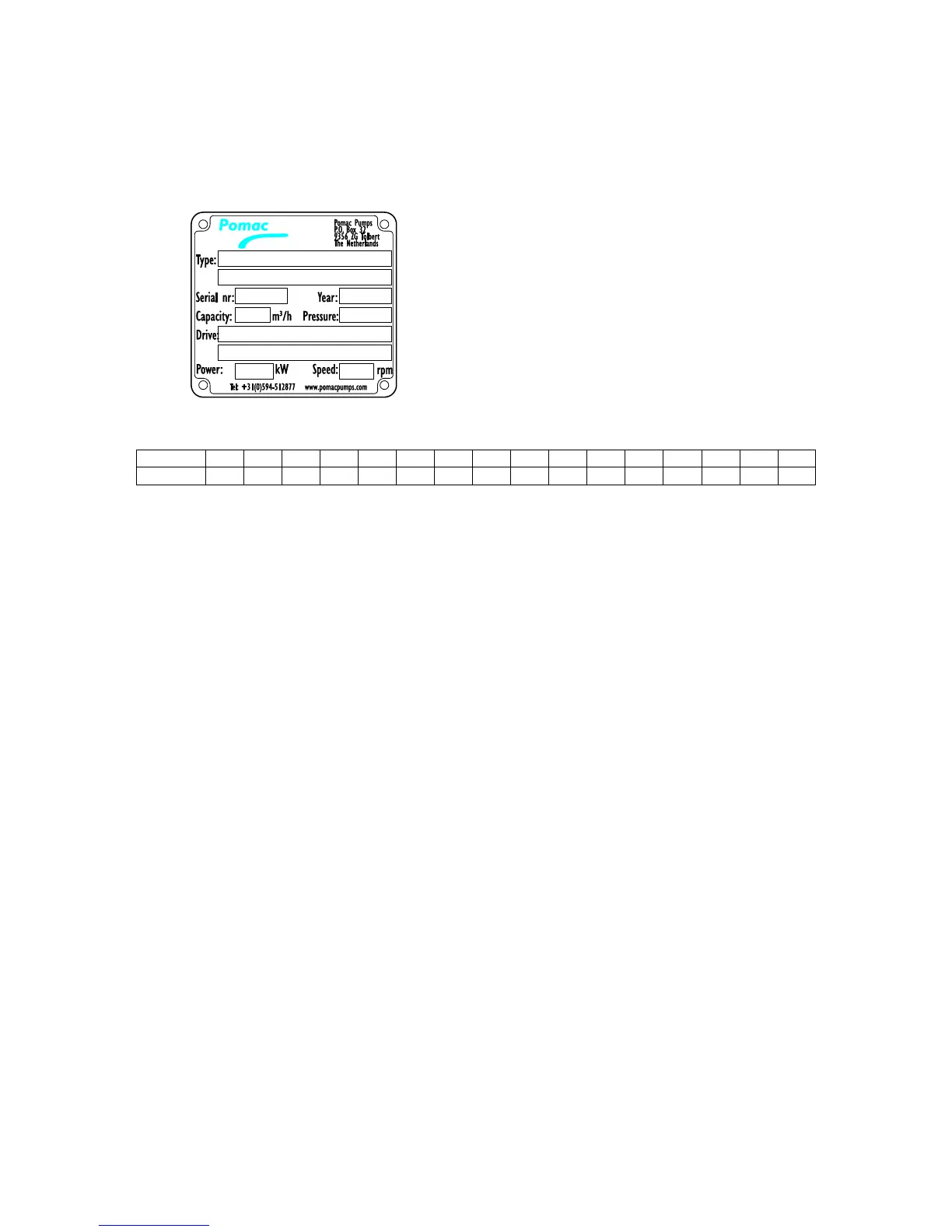
3.1. Pump identification
Each pump has a unique serial number and a type number. Both are stated on the type plate of
the pump.
The type number describes the set-up of the pump and is composed as follows:
*) PLPH in case of hydraulic drive,
PLPS in case of split pump casing.
Example: PLP 2-2 / M / 01 / 01 / M1 / V / V / P2 / S1 / C1 / O1 / G1 / H1 / V1 / R1 / W1
1. Pump type
1-3/4 = ¾” or DN15
1-1 = 1” or DN25
1-1,5 = 1,5” or DN40
15-2 = 2” or DN50
2-1,5 = 1,5” or DN40
2-2 = 2” or DN50
2-2,5 = 2,5” or DN65
3-2 = 2” or DN50
3-3 = 3” or DN80
3-4 = 4” or DN100
4-4 = 4” or DN100
2. Connection dimensions
I = Imperial system (Inch)
M = Metric system (DN)
3. Connection type suction side
01 = hygienic thread acc. to DIN 11851
02 = SMS 1145
03 = Tri-Clamp DIN32676
04 = Aseptic thread DIN 11864-1
05 = Aseptic flange DIN 11864-2
06 = flanges acc. to EN1092-1
07 = BSP-thread
08 = NPT-thread
09R = rectangular flange right side as seen from shaft end
09L = rectangular flange left side as seen from shaft end
09T = rectangular flange on top
10 = Aseptic Tri-Clamp DIN 11864-3
xx = acc. to client specification