User manual Pomac PLP Lobe pump
CE/PLP (1406) EN-12 35
14. Fit a bearing cartridge (15) to the rotor case, using Allen screws (14).
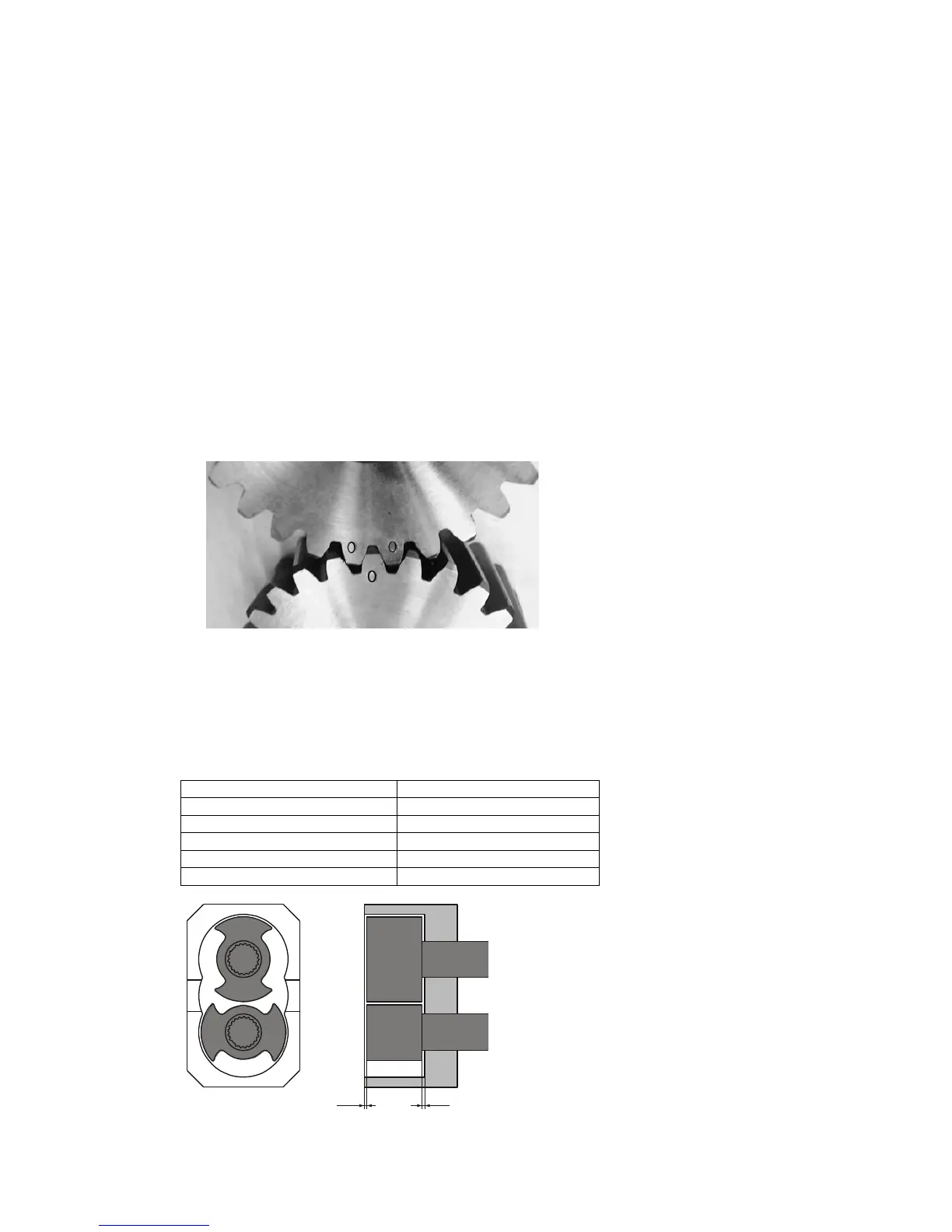
15. Fit the second bearing cartridge to the rotor case, using Allen screws. Ensure the marks on
the gears correspond with each other!
16. Place the shims (12) underneath the bearing cartridges in their original positions as marked
on the rotor case.
17. Fix the Allen screws of the bearing cartridges.
7.11. Adjusting the axial rotor clearance
The clearance between the rotor and the rotor case must be adjusted again in case one or more
of the following parts have been replaced:
⚫ shaft
⚫ pump casing
⚫ bearing
⚫ bearing cartridge
Do the following:
1. Fit a bearing cartridge (15) into the rotor case bore with Allen screws (14). Fix the bearing
cartridge temporarily with 2 screws.
2. Fit the other bearing cartridge into the rotor case bore with Allen screws. See to it that the
markings correspond to each other. Fix this bearing cartridge also temporarily with 2
screws.
3. Measure the depth of the rotor case.
4. Measure the distance between the front of the rotor case and the shaft shoulder against
which the rotor will rest.
5. The difference between both dimensions is called X.
6. Place the required thickness of shims (12) between the rotor case and the bearing cartridge
flange to get the clearance B (see table and figure below) within its required clearance limits.
Total shim thickness = X - B