User manual Pomac PLP Lobe pump
18 CE/PLP (1406) EN-12
⚫ For systems that convey liquid under vacuum, a non-return valve in the delivery line is
recommended. This prevents backflow of air or liquid.
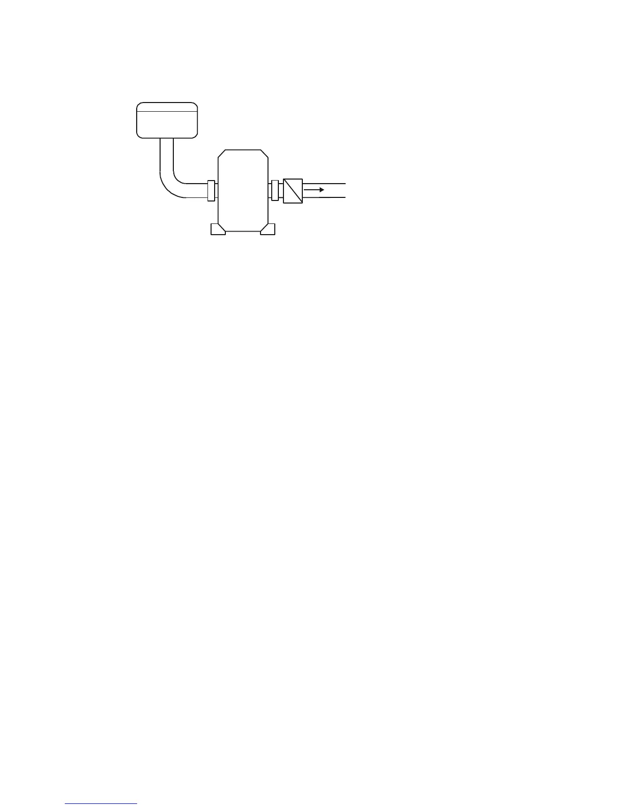
4.8. Pump with safety valve
If the pump is provided with a safety valve to the pump cover, it is compulsory to install a
pressure gauge at pressure side and a shut-off valve directly after the pressure gauge!
⚫ The pressure gauge must have a measuring range of at least 0-25 bar.
4.9. Pump-unit assembly
In case the pump is supplied as a single pump, it needs to be assembled to a drive and a
baseplate.
Do the following:
1. Place the pump onto the baseplate and fit it with retaining bolts.
2. Fit a coupling half to the pump shaft.
3. Fit the other half to the drive shaft of the drive.
4. Fit the drive to the baseplate. Leave a 3 mm gap between both coupling halves.
5. Place copper shims under the feet of the drive to bring it on a level with the pump. Fix the
drive.
6. Align the coupling according to the following instructions.
4.10. Coupling alignment
After the assembly and set-up of the pump-unit the alignment of the coupling needs to be
checked.
! Always check the alignment after hoisting the pump-unit up to its baseplate!
Misalignment can lead to excessive wear, increased motor temperature and noise level.
Check the alignment, using special alignment equipment, or do the following:
1. Place a ruler on the coupling. It must be adjacent to the entire width of the coupling halves,
see figure.
2. Repeat this check at 3 different positions around the coupling.
3. Check the alignment with a pair of outside callipers at 2 diametrically opposite positions of
the coupling sides, see figure.
4. If the measured values are outside the tolerance limits, slightly loosen the retaining bolts of
the drive and move the drive until the values are within their tolerance limits. Fix the retaining
bolts again.
5. When the coupling is well aligned mount the coupling guard.