User manual Pomac PLP Lobe pump
CE/PLP (1406) EN-12 39
7.14. Adjusting the timing of ‘quattro lobes’
If the pump is provided with so-called “quattro-lobes”, they must be adjusted with regard to
each other. Act as follows:
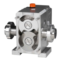
1. Ensure the Allen screws of the driven gear (see figure) are not completely tightened.
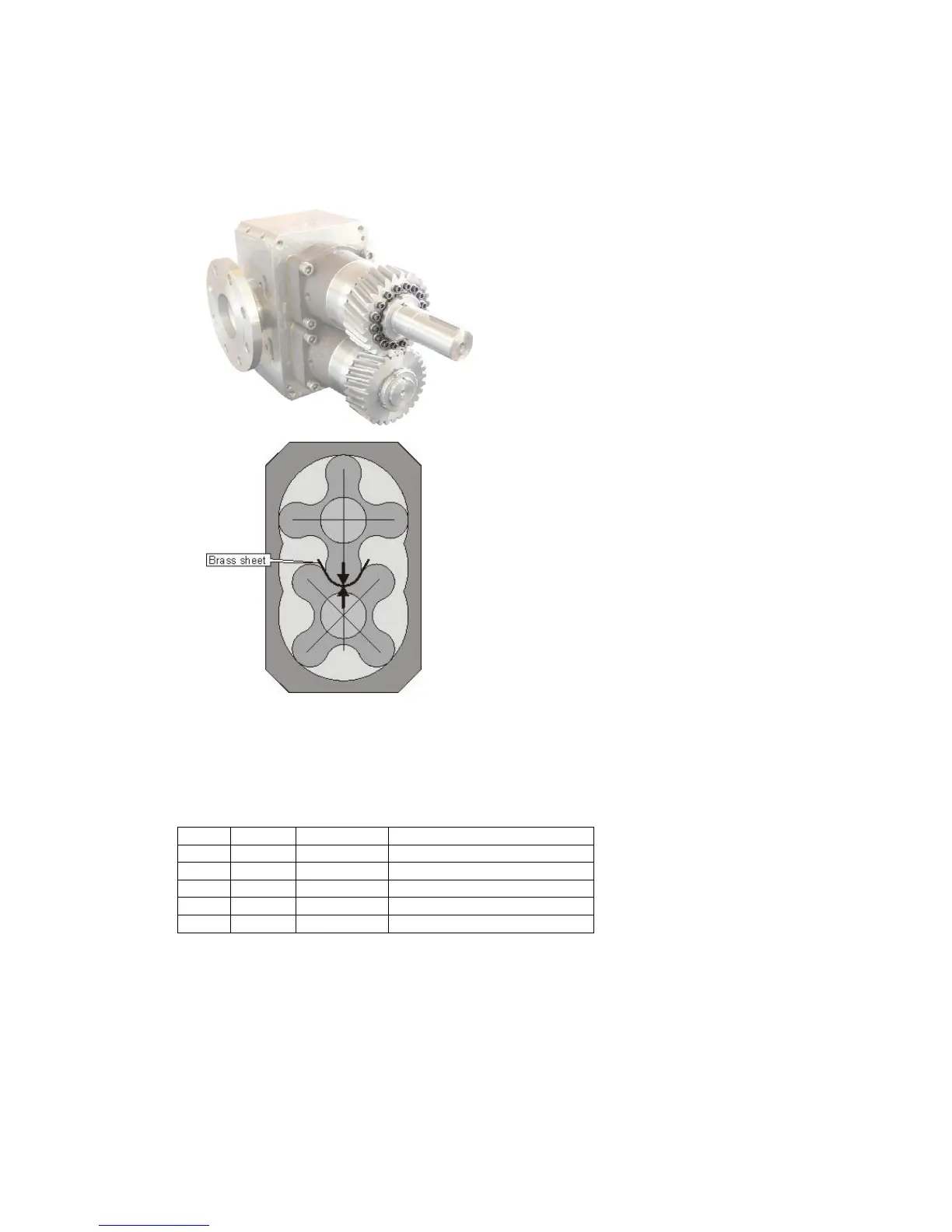
2. Rotate the pump shaft until the lobes are in the positions as shown below.
3. Measure the gap between the upper and lower rotor at the indicated spot, using a feeler
gauge.
4. Place a strip of brass sheet, with the thickness of the measured gap, between both lobes.
The lobes may no longer move with regard each other. If necessary use a thicker bass
sheet.
5. Tighten the Allen screws of the screw ring crosswise with the prescribed torque as indicated
below.
6. Remove the strip of brass sheet.
7.15. Front cover assembly
See paragraph 9.4 for drawing and parts list of the referenced parts.
1. Place the O-ring (4) in the front cover (3).
2. Fit the front cover to the rotor case and fix it with cap nuts (1)
3. Fit -in case they are disassembled- the feet (32) with Allen screws (33).