User manual Pomac PLP Lobe pump
CE/PLP (1406) EN-12 33
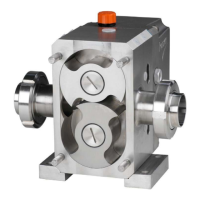
7.10. Gearbox assembly
See the sectional drawing with parts list in paragraph 9.4 for explanation of the item numbers.
For the shaft seals see paragraph 9.7.
! If the pump is provided with QUATTRO LOBES, the LOBE TIMING must always be
readjusted after every occasion the bearings have been disassembled! See paragraph
7.14 !
! Ensure all parts are clean and the working area is cleaned up!
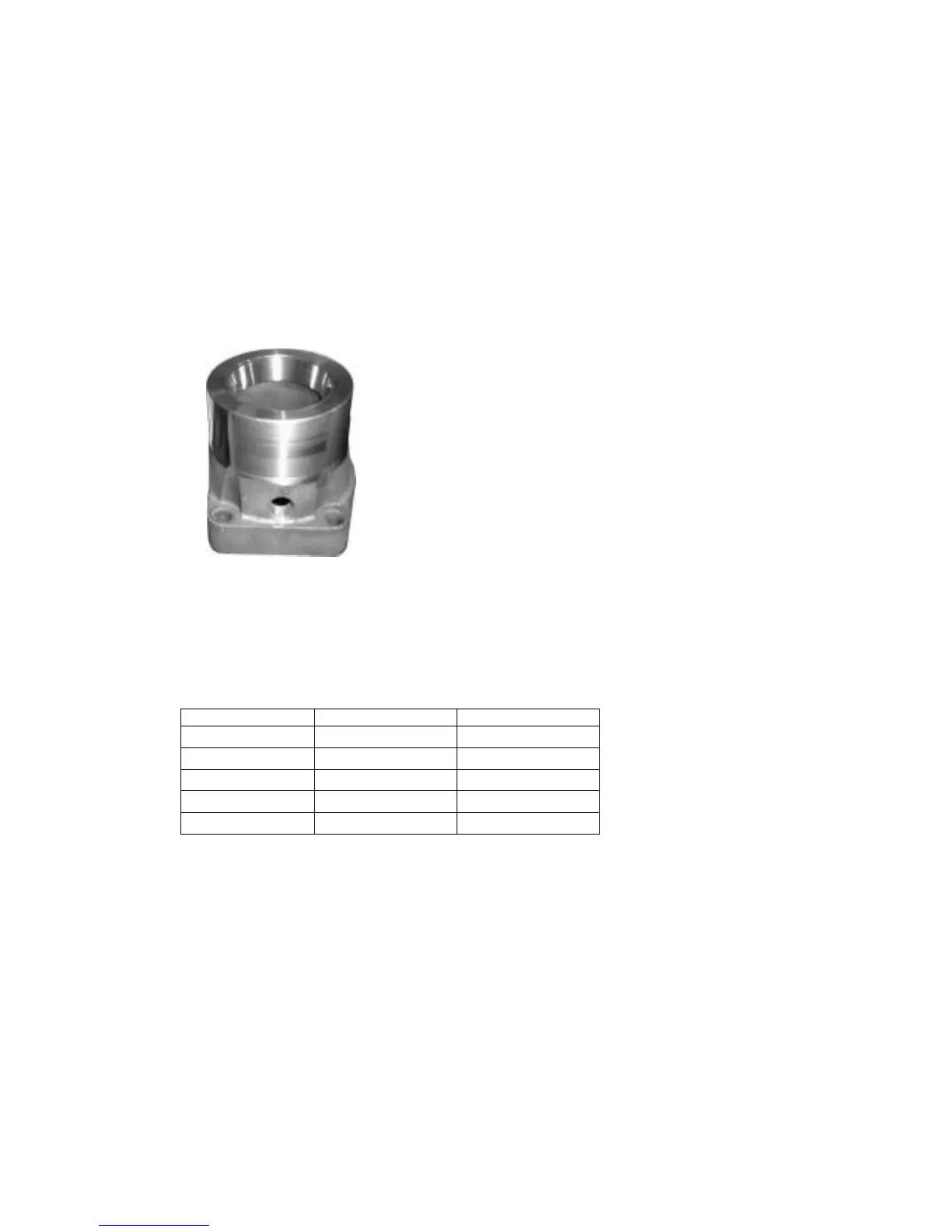
1. Fit the large and small bearing shells at both sides into the bearing cartridges (15).
2. Heat the larger bearings (13) and fit these to the shafts. Push the bearings firmly and let
them cool down.
3. Put the shaft vertically on the spline side and place the bearing cartridge with the bearing
shells onto the shaft.
4. Heat the smaller bearings (16) and fit these to the shafts. Push the bearings firmly and let
them cool down.
5. Fit a key (18) in each shaft. See following table for the correct dimensions.
If quattro lobes are mounted:
6. Place the gear ring over the hub of the adjustable gear. Ensure the key way in the hub and
the marks on the gear ring are placed opposite to each other (so the key way at “12
o’clock” and the marks at “6 o’clock”)
7. Apply a drop of oil on the Allen screws and screw them into the gear ring. Tighten the Allen
screws by hand.
8. Fit the gears (17 and 29) to the shafts, its marks facing towards the rear side (drive side).
The gear with right hand helix (17) has 2 marks and must be fitted to the drive shaft (23).
The gear with left hand helix (29) has 1 mark and must be fitted to the lay shaft (30).