Hardware Configuration
RUBY-9715VG2AR User’s Manual 2-18
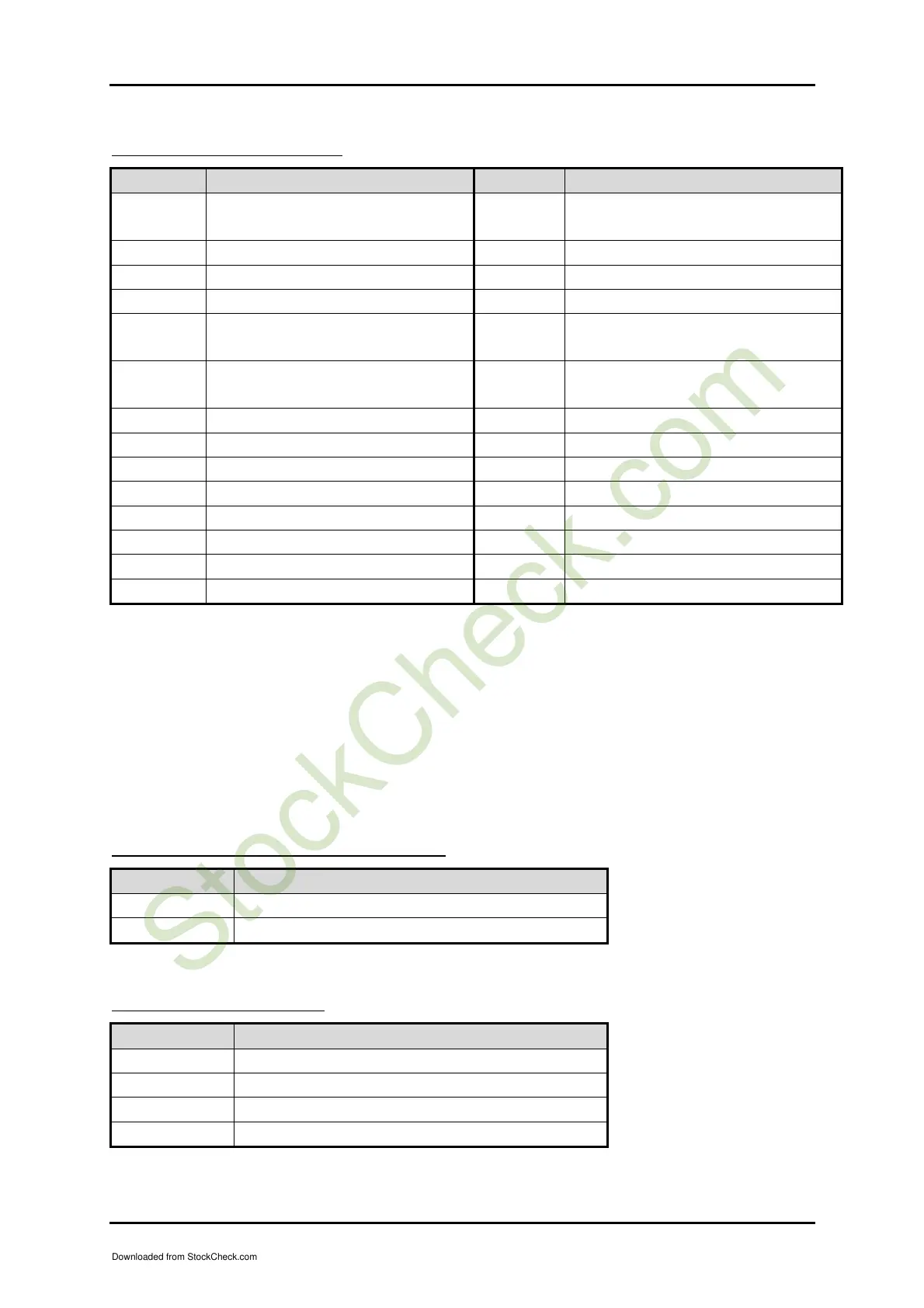
J19 : Front Panel Connector
PIN No. Signal Description PIN No. Signal Description
1 150 ohm Pull-High VCC (HDD
LED+)
2 330 ohm Pull-High Stand-by
VCC (Power LED+)
3 HDD LED - 4 N/C
5 N/C 6 Power LED -
7 N/C 8 N/C
9 150 ohm Pull-High Stand-by
VCC
10 N/C
11 ATX Power On Control (PS-
ON) (Active High)
12 N/C
13 Ground 14 VCC
15 N/C 16 Ground
17 Reset Signal Input (Active low)
18 Ground
19 Ground 20 Speaker-out
21 LED_LAN_ACT+ 22 LED_LAN2_ACT+
23 LED_LAN_ACT- 24 LED_LAN2_ACT-
25 LED_LAN_SPEED+ 26 LED_LAN2_SPEED+
27 LED_LAN_SPEED- 28 LED_LAN2_SPEED-
Note:
The pull-high voltage of external speaker is limited at 5V maximum.
Power Button : J19-pin 9 and J19-pin 11
Reset Button : J19-pin 17 and J19-pin 19
Power LED : J19-pin 2 and J19-pin 6
Speaker :J19-pin 14 and J19-pin 20
HDD LED : J19-pin 1 and J19-pin 3
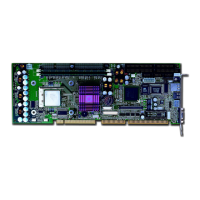
J22 : External Wake On Ring Connector
PIN No. Signal Description
1 Ring Signal Input (Active low)
2 Ground
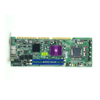
J23 : 4-pin Fan Connector
PIN No. Signal Description
1 Ground
2 +12V
3 Fan Speed Detecting signal
4 Fan Control Signal
Downloaded from StockCheck.com