Hardware Configuration
RUBY-9715VG2AR User’s Manual 2-19
Note:
The fan must be a 12V fan. And there is no over current protection.
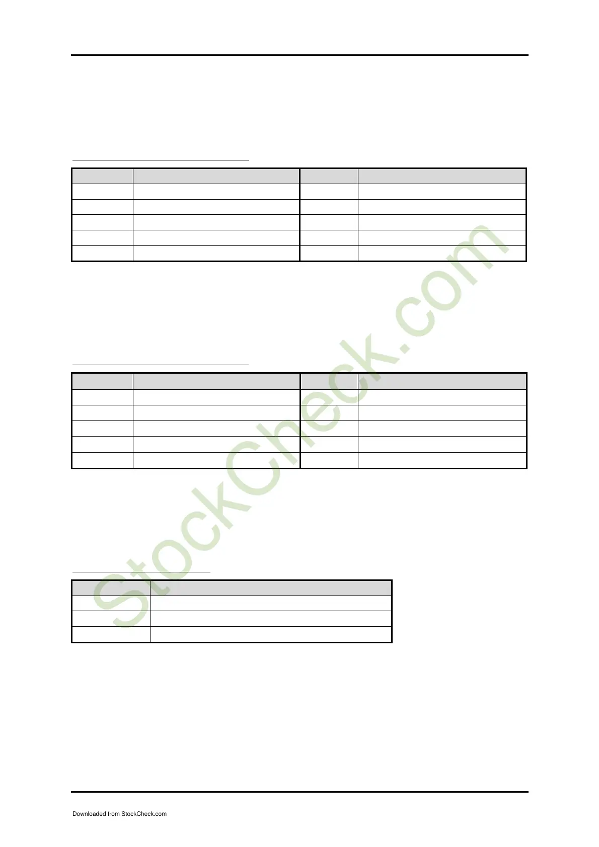
J24 : 3rd pairs of USB Connector
PIN No. Signal Description PIN No. Signal Description
1 5V Dual 2 Frame Ground
3 USB4- 4 Ground
5 USB4+ 6 USB5+
7 Ground 8 USB5-
9 Frame Ground 10 5V Dual
Note:
5V Dual is always available. It's supplied by either 5V VCC power source in normal
operation mode or 5V standby power source in standby mode
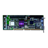
J26 : 4th pairs of USB Connector
PIN No. Signal Description PIN No. Signal Description
1 5V Dual 2 Frame Ground
3 USB6- 4 Ground
5 USB6+ 6 USB7+
7 Ground 8 USB7-
9 Frame Ground 10 5V Dual
Note:
5V Dual is always available. It's supplied by either 5V VCC power source in normal
operation mode or 5V standby power source in standby mode
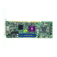
J27 : 3-pin Fan Connector
PIN No. Signal Description
1 Ground
2 +12V
3 Fan Speed Detecting signal
Note:
The fan must be a 12V fan. And there is no over current protection.
Downloaded from StockCheck.com