EasyManuals Logo

Power Electronics SD700 Series Hardware And Installation Manual

Power Electronics SD700 Series
91 pages
To Next Page IconTo Next Page
To Previous Page IconTo Previous Page
Page #33 background imageLoading...
Page #33 background image
POWER ELECTRONICS
MECHANICAL INSTALLATION
31
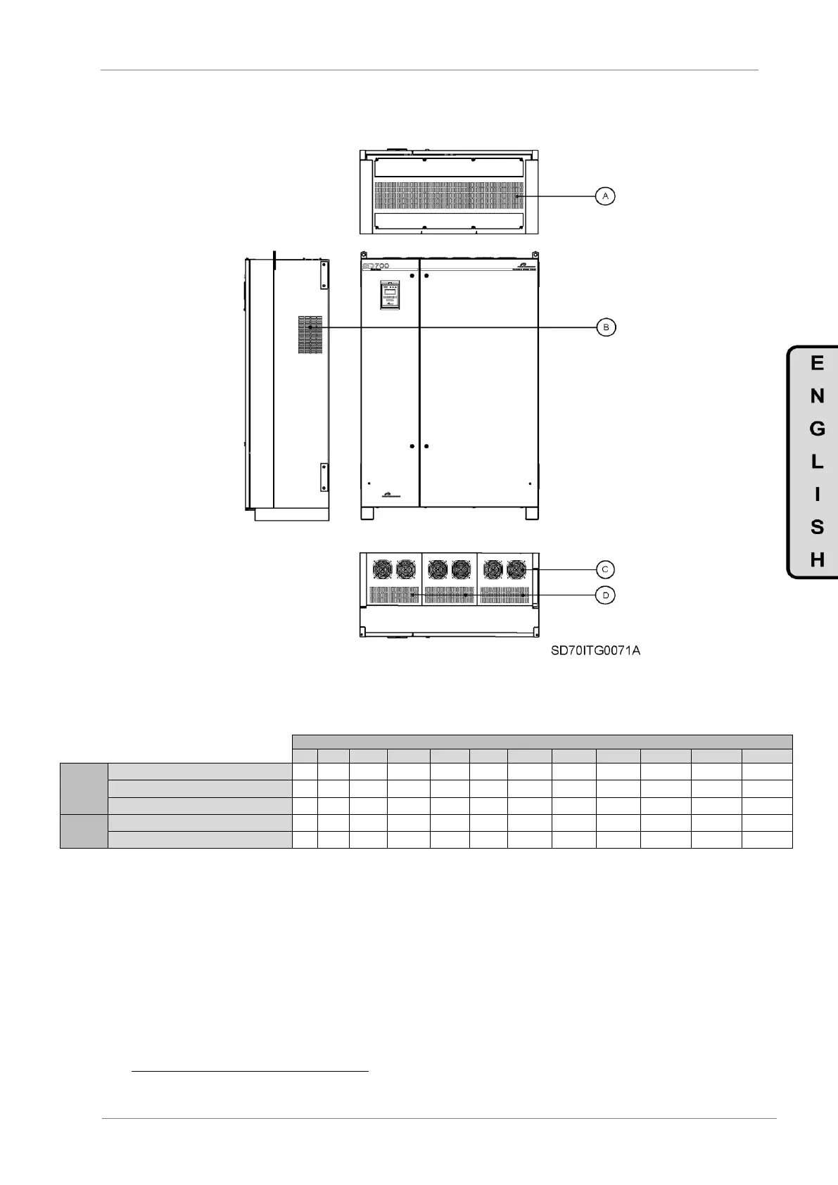
The following figure identifies the gratings and fans of the different cooling areas.
Figure 5.6 SD700 gratings and fans
FRAMES
ID
1
2
3
4
5
6
7
8
9
10
11
AREA 2
OPERATION FLOW (m
3
/h) (*)
D
64-77
239-287
306-367
342-410
396-475
486-583
720-864
972-1166
1458-1750
2178-2614
2898-3478
INLET GRATING NET SECTION (m
2
)
A
0.081
0.016
0.025
0.031
0.034
0.064
0.101
0.123
0.192
0.303
0.369
OUTLET GRATING NET SECTION (m
2
)
D
0.003
0.013
0.017
0.019
0.022
0.027
0.040
0.054
0.081
0.121
0.161
AREA 3
OPERATION FLOW (m
3
/h)
C
-
-
-
180
360
720
1080
1440
2160
3240
4320
INLET GRATING NET SECTION (m
2
)
B
0.081
0.016
0.025
0.031
0.034
0.041
0.041
0.041
0.122
0.122
0.122
Heat dissipation
The heat generated by the SD700 depends on the carrier frequency (Hz), the grid frequency and the load.
It could be estimated by the following equation. Rated power condition is the worst case.
P
loss
[W] = 0,02 · P
motor
[W]
(*)The air velocity, which passes through the gratings, varies between 5 and 6 m/s depending on the blocking of the
gratings.

Other manuals for Power Electronics SD700 Series

Questions and Answers:

Question and Answer IconNeed help?

Do you have a question about the Power Electronics SD700 Series and is the answer not in the manual?

Power Electronics SD700 Series Specifications

General IconGeneral
BrandPower Electronics
ModelSD700 Series
CategoryInverter
LanguageEnglish

Related product manuals