7. CONTROL CONNECTION
7.1. Wiring recommendations
Before planning the installation, follow the next recommendations. The parallel cable routing should be
minimized and the distance between the control wiring and the power wiring should be maximized. It is
recommended to route control cables with different voltages in separately cable racks, trays or ducts.
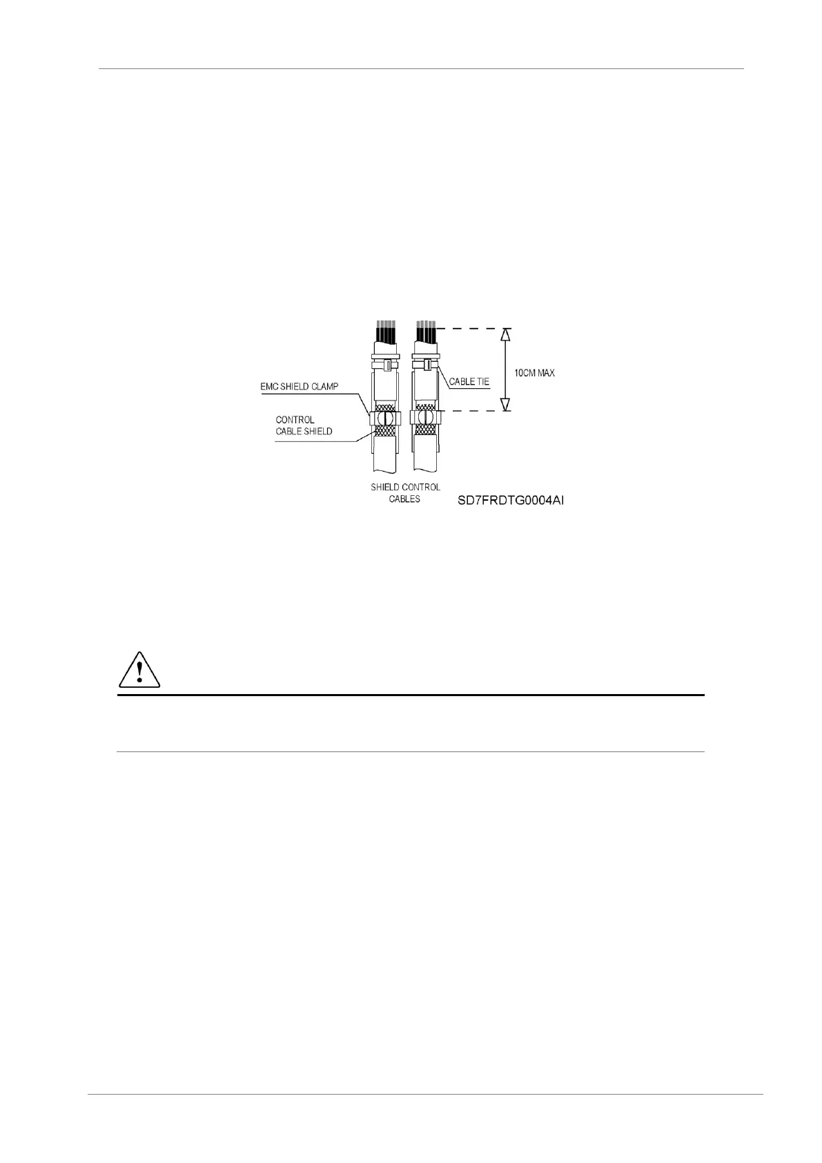
It is recommended to use shielded twisted cable for all the data, signal or control cables that came out from
the variable speed drive, with the properly shield bonding to ground. To ensure an effective shield bonding,
it is recommended to include in the SD700 front metal panel of the control board, EMC shield clamps that
ensure a 360º effective shield bonding.
Figure 7.1 Shield bonding
Digital signal cables must be grounded at both ends of the cable. It is recommended to use independent
shielded cables for digital and analogue signals. When using multiple analogue signals do not use common
return for them. If a low-interference is experienced (hum loops) using analogue signals disconnect the
shield grounding from one of the ends. The maximum section for the control cables is 2.5mm² and the
recommended tightening torque is 0.4Nm.
Although the control board is insulated galvanically, for safety reasons it is recommended not to modify the
wiring while the equipment is connected to the input power supply.
CAUTION
Changes of control wiring or bridges should be performed following the safety instructions
indicated before. Otherwise, it could cause damage to the equipment and lead to injury to people.
 Loading...

