7.2. Control board terminals description
CAUTION
Changes of control wiring or bridges should be performed at least 10 minutes after
disconnecting the input power and after checking the DC Link voltage is discharged with a meter
(below 30VDC). Otherwise, you may get an electric shock.
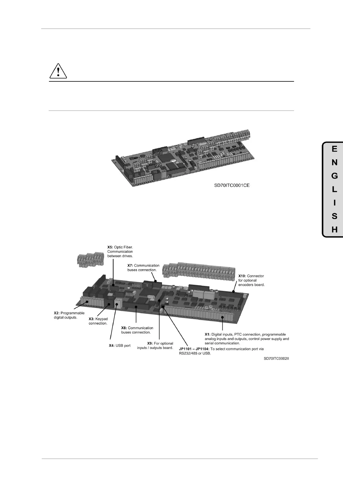
Figure 7.2 Control board of SD700
The user will have only access to the inverter control board that is equipped with the user interface ports
and connectors. It integrate as standard PTC connection, analogue inputs and outputs, digital inputs and
outputs, DC external input power supplies, RS485, RS232 and USB communication and display ports.
Moreover, the board is ready for the connection of optional boards such as I/O expansion board, encoder
board, communication boards, fiber optic board, etc.
Figure 7.3 Location and description of user connectors
 Loading...

