The following figure provides an overview of the standard wiring of control terminals through the X1 and
X2 user connectors.
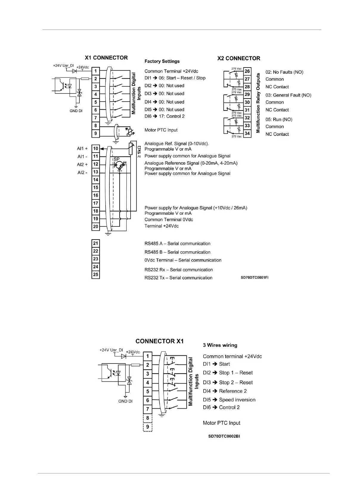
Figure 7.4 Example of control terminals standard wiring
Digital inputs can be configured individually or collectively. Analogue inputs can be configured as
comparators. Details on varying standard configurations are available in the Software manual to assist the
user. The following figure shows typical wiring configuration for a 3-wire start / stop push button system.
Figure 7.5 Wire control terminals wiring
 Loading...

