6.9.2. Terminals of the Resistor for Dynamic Brake
The terminals of the braking resistors are:
Connection terminals to connect the resistor to the terminals of the dynamic
brake built in the drive.
Thermal sensor of the resistor. The status of which will change according to
the temperature.
- For normal temperature (ambient): Normally closed (NC) (TH1 – TH2
closed contact).
- In case of resistor over temperature: Normally open (NO) (TH1 – TH2
open contact).
Connect this signal to a terminal of one digital input of the drive configured
as ‘external fault’.
[1]
Terminals TH1 and TH2 will be available when the used braking resistor is equipped with thermal sensor.
Note: It is recommended to use braking resistors equipped with thermal sensors. Connect it to one digital input
of the drive and configure this input as ‘external fault’.
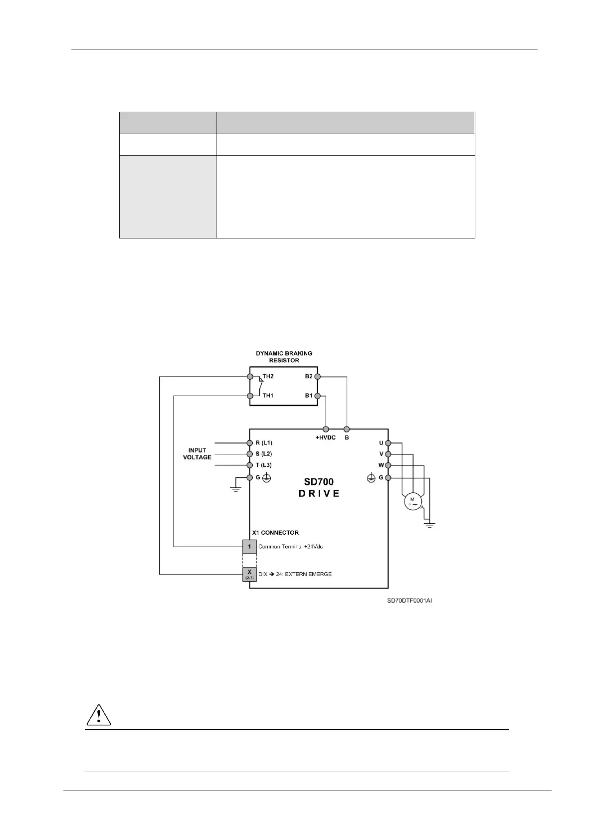
6.9.3. Connection Drawing
The connection between the optional external resistor for the built-in dynamic brake and the drive
is shown in the following figure.
Figure 6.18 Connection drawing of the resistor for the dynamic brake in equipments of Frames 1 and 2
Notes:
The braking resistor should be non-inductive.
To connect the sensor to the drive, it is recommended to use shielded cable.
The maximum cable length between the drive and the external braking resistor is 20m. For other
configurations, contact with Power Electronics.
CAUTION
Do not touch the braking resistor during the drive operation since it could be very hot (more than
150ºC).
 Loading...

