6.9. Dynamic Braking Resistors for Equipments of Frames 1
and 2
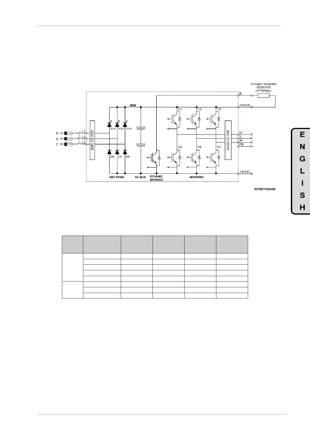
The equipments of Frames 1 and 2 include the built-in dynamic brake as standard. The user should only
connect a resistor between terminals +HVDC and B, as the following drawing shows.
Figure 6.17 Power electronics for equipments of Frames 1 and 2
6.9.1. Resistor Values for Dynamic Brake (Optional)
Motor Power
(kW) at
400VAC
Dynamic
Braking
Resistor (Ω)
Power of
Braking
Resistor (kW)
Note: This table is based on ED (Enable Duty) of 100%. For other ED’s different than 100%, it will be used braking
resistor with the same value in ohms and their power will be calculated by multiplying their power value at 100% (table
value) by the new ED. Enable Duty means the time operated by the resistor (regeneration). Resistors for 100% of ED =
continuous operation. For example, in case of ED of 30%, it will be multiplied by 0.3.
 Loading...

