8.2. Hardware technical specifications
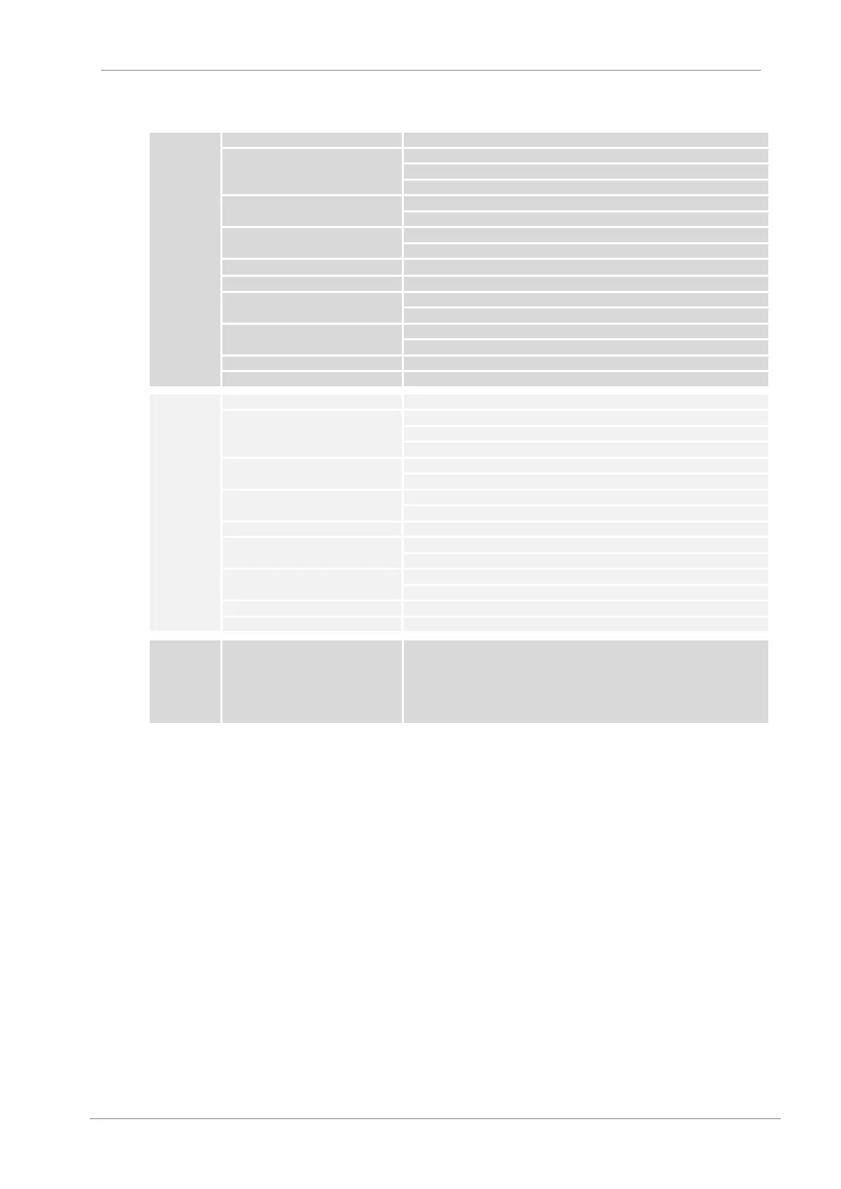
3 cables, optically insulated, half duplex, RS232 single ending
24 RS232 Rx (receiving line)
25 RS232 Tx (transmitting line)
'1' logical ≤ 6.5V regarding to 0V
'0' logical ≥ 6.5V regarding to 0V
± 50VDC regarding to the earth
Programmable inputs via Modbus
2 programmable analogue inputs (0 – 10V, ±10V, 0 – 20mA, 4 – 20mA)
Programmable outputs via Modbus
2 programmable analogue outputs (0 – 10V, ±10V, 0 – 20mA, 4 – 20mA)
Max. number of SD700 in network
2 cables, optically insulated, half duplex, RS485 differential mode
'1' logical = +5V differential
'0' logical = -5V differential
'1' logical = +5V differential
'0' logical = -5V differential
± 50VDC regarding to the earth
Programmable inputs via Modbus
2 programmable analogue inputs (0 – 10V, ±10V, 0 – 20mA, 4 – 20mA)
Programmable outputs via Modbus
2 programmable analogue outputs (0 – 10V, ±10V, 0 – 20mA, 4 – 20mA)
Max. number of SD700 in network
Connector: USB 1.1 and 2.0 type B.
Controller FTDI chip
Model FT232BM
For the correct operation of the USB connection, you should install the proper
drivers. For this, you only need to access to the information of the proper model
in:
http://www.ftdichip.com/Drivers/VCP.htm
From here, you can download the required files and complete their correct
installation.
Note: Installation in the driver Host of the SD700 USB, USB device of the SD700 will be detected by operating systems
XP and 2000, it is only necessary to indicate the driver at the time of the installation. In case of operating systems
before W98 / Me, execute a search of new Hardware in the device administrator, and complete the installation by
indicating the drivers when the computer requires them.
 Loading...

