EasyManuals Logo

Power Electronics SD700 Series Hardware And Installation Manual

Power Electronics SD700 Series
91 pages
To Next Page IconTo Next Page
To Previous Page IconTo Previous Page
Page #41 background imageLoading...
Page #41 background image
POWER ELECTRONICS
POWER CONNECTION
39
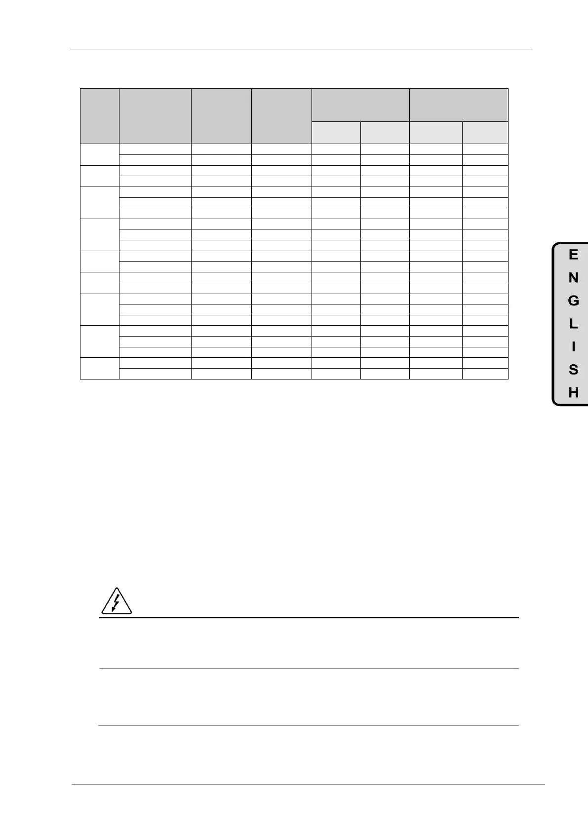
6.3.2. Recommended Cable Section for 690VAC
FRAME
CODE
I(A)
Rated
Power (kW)
at 690VAC
Recommended
Cable Section
per Phase
Recommended
Cable Section
for Earth Wire
AWG /
kcmil
mm²
AWG /
kcmil
mm²
3
SD70052 6X
52
45
3 1
16 25
3 1
16 25
SD70062 6X
62
55
3 1
16 25
3 1
16 25
4
SD70080 6X
80
75
100
95
100
95
SD70105 6X
105
90
2/0 4/0
50 95
2/0 4/0
50 95
5
SD70130 6X
130
110
3/0 300
70 120
3/0 300
70 120
SD70150 6X
150
132
3/0 300
70 120
3/0 300
70 120
SD70170 6X
170
160
3/0 300
95 150
3/0 300
95 150
6
SD70210 6X
210
200
300 500
120 240
300 500
120 240
SD70260 6X
260
250
2 x 300
2 x 150
2 x 300
2 x 150
SD70320 6X
320
315
2 x 500
2 x 185
2 x 500
2 x 185
7
SD70385 6X
385
355
2 x 500
2 x 240
2 x 500
2 x 240
SD70460 6X
460
450
2 x 500
2 x 240
2 x 500
2 x 240
8
SD70550 6X
550
500
2 x 500
2 x 240
2 x 500
2 x 240
SD70660 6X
660
630
3 x 500
3 x 240
3 x 500
3 x 240
9
SD70750 6X
750
710
4 x 500
4 x 240
4 x 500
4 x 240
SD70840 6X
840
800
4 x 500
4 x 240
4 x 500
4 x 240
SD70950 6X
950
900
4 x 500
4 x 240
4 x 500
4 x 240
10
SD71140 6X
1140
1000
6 x 500
6 x 240
6 x 500
6 x 240
SD71270 6X
1270
1200
6 x 500
6 x 240
6 x 500
6 x 240
SD71420 6X
1420
1400
7 x 500
7 x 240
7 x 500
7 x 240
11
SD71500 6X
1500
1500
8 x 500
8 x 240
8 x 500
8 x 240
SD71800 6X
1800
1800
8 x 500
8 x 240
8 x 500
8 x 240
Note: Cable must be suitable for a permanent Tª >75ºC. Use 600V cables for up to 500Vac rated voltage.
For 525Vac and 690Vac phase to phase rated equipment use 1kV cables. However this is only a
recommendation. You must follow the local regulation.
6.4. Ground connection
Before connecting the power conductors, be sure that the chassis of the drive and the adjoining cabinets
are connected to ground through the dedicated (PE) terminals. They are situated at both sides of the bottom
metallic walls of the drive and they are labelled with the appropriate ground connection. Check section
“6.10 Power Terminals”.
Motor’s chassis grounding must be connected to the drive. In other words, connect the motor’s ground
conductor to the PE output terminal of the drive and not to the installation’s ground. We recommend that
the cross section of the motor’s ground conductor (PE) should have at least the cross section of the active
conductor (U, V, W). Additionally, it should be installed following the recommendations indicated in section
“6.3 Power Connection and wiring”.
When connecting the earth, ensure that all connected terminal lugs are securely tight and protected from
mechanical forces. The tightening torque in case of M10 PE terminals is 40Nm.
CAUTION
For safety reasons it is determinant to measure the grounding resistance of the plant itself. This
must be established before the first start up of the plant and with the drive disconnected.
It is responsibility of the installer to provide the adequate number, type and cross section
grounding conductor alongside with the characteristics of the drive used and of the Plant in order to
minimize the grounding resistance, that comply with the local and national regulation.

Other manuals for Power Electronics SD700 Series

Questions and Answers:

Question and Answer IconNeed help?

Do you have a question about the Power Electronics SD700 Series and is the answer not in the manual?

Power Electronics SD700 Series Specifications

General IconGeneral
BrandPower Electronics
ModelSD700 Series
CategoryInverter
LanguageEnglish

Related product manuals