DESCRIPTION OF PROGRAMMING PARAMETERS
Parameter /
Default Value
7 Sma1=+10.0l/s
[3]
SENS1 HIGH RANGE
G4.2.7 /
Maximum range
of sensor 1
G4.2.5 to
+3200
Engineering
units
It sets the maximum units value of the sensor connected to analogue input 1. This
value should also correspond to the maximum voltage or current level of the
sensor set in 'G4.2.6 INmax1'.
Note: This value should be checked if the units are changed in 'G4.2.2 SENSOR
1'. For this, it is necessary to set this value in open loop and close loop
configurations.
8 SPD LO1=+0%
SPD LO RNG AIN1
G4.2.8 / Speed
for the minimum
range of
Analogue Input 1
It allows scaling of the speed reference to correspond with the minimum range of
the analogue input 1 as set in 'G4.2.4 INmin1'.
The value is a percentage of the motor rated speed.
9 SPD HI1=+100%
SPD HIG RNG AIN1
G4.2.9 / Speed
for the maximum
range Analogue
Input 1
It allows scaling of the speed reference to correspond with the maximum range of
the analogue input 1 as set in 'G4.2.6 INmax1'.
The value is a percentage of the motor rated speed.
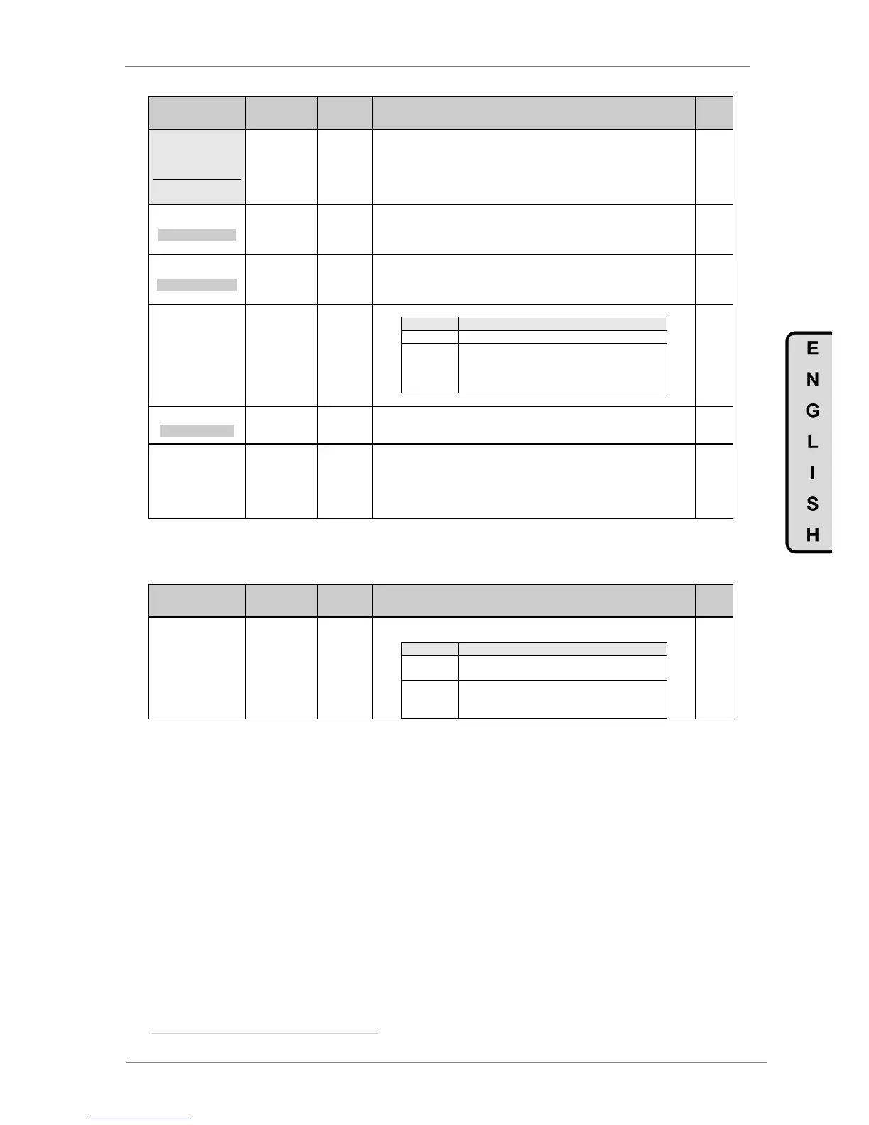
G4.2.14 /
Protection for
Analogue Input 1
loss
To set the drive stop mode when a loss of the analogue input 1 signal occurs.
When the analogue input level decreases down
to zero value, sensor will be considered damaged
and the drive will stop generating a fault 'F42
AIN1 LOSS'.
15 1_Z BAND=OFF
AIN1 ZERO BAND
G4.2.15 / Zero
band filter for
Analogue Input 1
Filtering of analogue input 1 signal. Setting this value we can filter analogue input
1 to avoid possible electrical noise preventing the analogue reading a zero value.
16 FILTER1=OFF
AIN1 STABIL FILT
G4.2.16 / Low
Pass filter for
Analogue Input 1
It allows filtering the Analogue Input 1 signal. Setting the value of this time
constant we can eliminate possible instabilities in the value of the same ones due
to noise, wiring faults, etc.
Note: When applying a Low Pass filter to any analogue signal, a delay time in the
own signal is generated. This delay time is the value of the configured time
constant approximately.
4.4.3. Subgroup 4.3 – S4.3: Analogue Input 2
Parameter /
Default Value
G4.3.1 / Sensor
of Analogue
Input 2 enable
It allows user to configure analogue input 2 for use with a sensor and activates the
parameters which are necessary to set it up. See G4.3.2 up to G4.3.7.
The analogue input will remained scaled in
defaults units (%).
The analogue input and any variables relating to
the analogue input will be configured in the
engineering units selected in G4.3.2.
[3]
Available only when 'G4.2.1 SENSOR 1 = Y'.