DESCRIPTION OF PROGRAMMING PARAMETERS
Parameter /
Default Value
G4.1.10 / Multi-
function Digital
Input 6
configuration
Note: Coming from the previous page.
It activates or deactivates dynamic
brake unit. (NO)
To select the alternative starting
mode (Ramp / Spin) (NO)
To select the alternative current
limit. (NO)
To generate the fault „F56
EMERGEN.STOP‟. (NC). See Note.
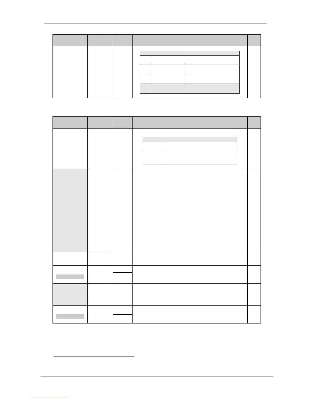
Parameters 70 and 75 available with the pump software.
4.4.2. Subgroup 4.2 – S4.2: Analogue Input 1
Parameter /
Default Value
G4.2.1 / To
enable sensor of
Analogue Input 1
It allows user to configure analogue input 1 for use with a sensor and activates the
parameters which are necessary to set it up. See G4.2.2 up to G4.2.7.
The analogue input will remain scaled in default
units (%).
The analogue input and any variables relating to
the analogue input will be configured in the
engineering units selected in G4.2.2.
G4.2.2 /
Selection of
sensor 1 units
%
l/s
m³/s
l/m
m³/m
l/h
m³/h
m/s
m/m
m/h
Bar
kPa
Psi
m
ºC
ºF
ºK
Hz
rpm
It allows selection of different units of measurement for analogue input 1
according to the sensor that is used.
If this parameter is modified, the minimum and maximum values of the sensor
range must be adjusted to ensure correct configuration. Therefore, the following
set values should be checked:
'G4.2.5 Smi1=+0.0l/s' Minimum range of sensor.
'G4.2.7 Sma1=+10.0l/s' Maximum range of sensor.
G4.2.3 /
Analogue Input 1
format
It allows configuration of the analogue input 1 format for either a voltage or current
signal. Set according to the sensor that will be used.
4 INmin1=+0V
AIN1 LOW RANGE
G4.2.4 /
Minimum range
of Analogue
Input 1
-10V to G4.2.6
+0mA to
G4.2.6
It determines the minimum voltage or current value for analogue input 1. Set
according to the characteristics of the sensor that will be connected.
5 Smi1=+0.0l/s
[3]
SENS1 LOW RANGE
G4.2.5 /
Minimum range
of sensor 1
-3200 to
G4.2.7
Engineering
units
It sets the minimum units value of the sensor connected to analogue input 1. This
value should also correspond to the minimum voltage or current level of the
sensor set in 'G4.2.4 INmin1'.
Note: This value should be checked if the units are changed in 'G4.2.2 SENSOR
1'. It will be set to operate in open loop and close loop.
6 INmax1=+10V
AIN1 HIGH RANGE
G4.2.6 /
Maximum range
of Analogue
Input 1
G4.2.4 to
+10V
G4.2.4 to
+20mA
It determines the maximum voltage or current value for analogue input 1. Set
according to the characteristics of the sensor that will be connected.
Note: The user can choose this option independently of the selected program (STÁNDARD or PUMP) or the control
mode used (LOCAL, REMOTE, and SERIAL COMMS).
[3]
Available only when 'G4.2.1 SENSOR 1 = Y'.