DESCRIPTION OF PROGRAMMING PARAMETERS
4.8.2. Subgroup 8.2 – S8.2: Analogue Outputs
Parameter /
Default Value
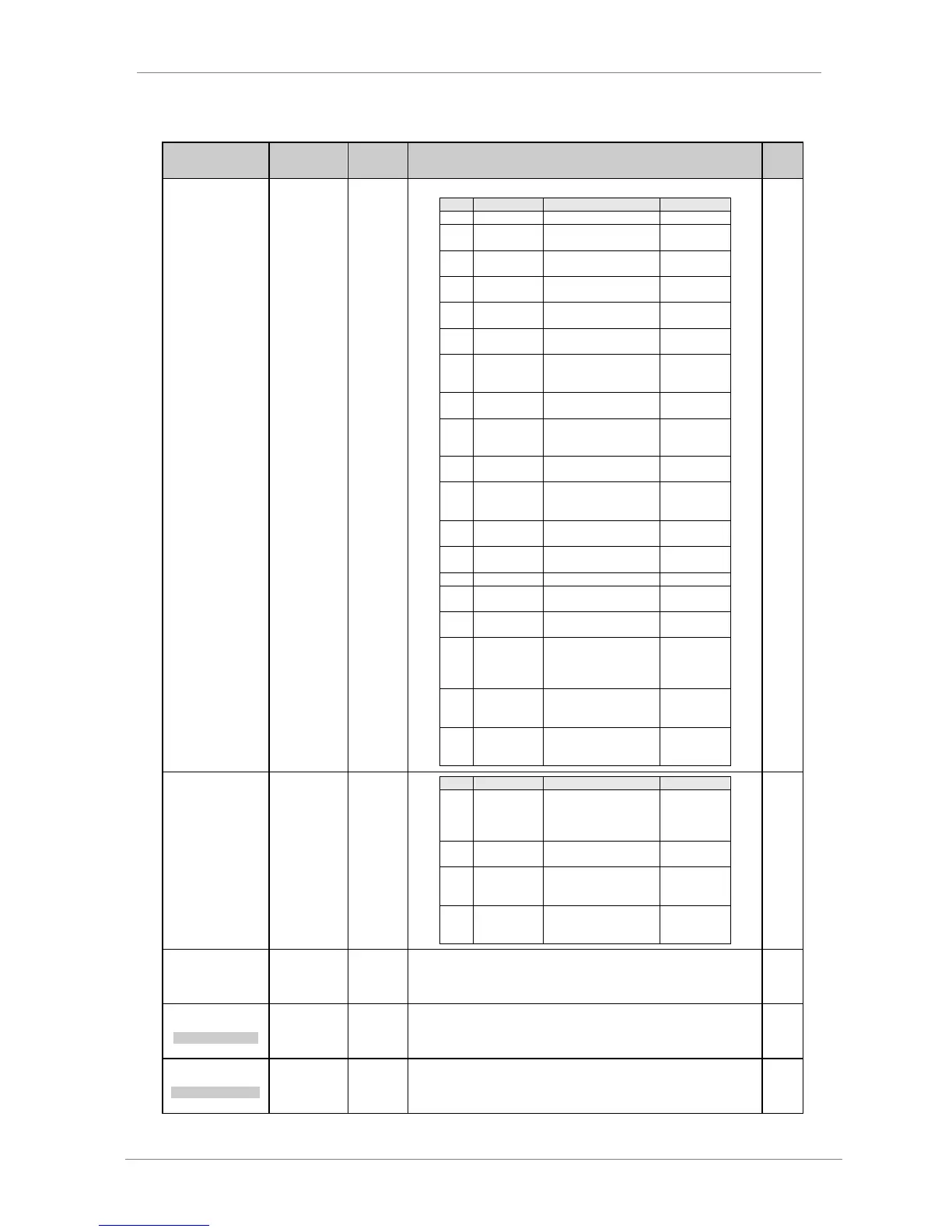
G8.2.1 / Mode
selection for
Analogue Output
1
Analogue output is programmable according to the following table:
Signal proportional to the
motor speed.
Signal proportional to the
motor current.
Signal proportional to the
motor voltage.
Signal proportional to the
motor power.
Signal proportional to the
motor torque.
Signal proportional to the
motor power factor.
Signal proportional to the
motor temperature.
Signal proportional to the
input frequency.
% Input
frequency
(50Hz=100%)
Signal proportional to the
input voltage.
% Equipment
rated voltage
Signal proportional to the
DC Bus voltage.
Signal proportional to the
drive temperature.
Signal proportional to the
speed reference.
Signal proportional to the
reference in PID mode.
Signal proportional to the
feedback in PID mode.
Signal proportional to the
error (difference
between reference and
feedback) in PID mode.
Analogue input 1 signal
is transferred to
analogue output.
Analogue input 2 signal
is transferred to
analogue output.
G8.2.1 / Mode
selection for
Analogue Output
1
Analogue signal
proportional to the read
flow through analogue
input or pulse input.
It forces the output to
maximum value.
Signal proportional to the
motor speed without sign
(absolute value).
Signal proportional to the
motor torque without
sign (absolute value).
G8.2.2 / Format
selection for
Analogue Output
1
Analogue output 1 is programmable in one of four possible formats according to
the system requirements.
3 MIN1 RNG=+0%
MIN RANG ANAOUT1
G8.2.3 / Low of
range selection
Analogue Output
1
Minimum level of analogue output 1.
Minimum level setting can be higher than the maximum level setting. This allows
the user to achieve inverse scaling. i.e. an increase in magnitude of the analogue
input would result in an output frequency decrease and vice versa.
4 MAX1 RNG=+100%
MAX RANG ANAOUT1
G8.2.4 / High
range selection
of Analogue
Output 1
Maximum level of analogue output 1.
Maximum level setting can be lower than the minimum level setting. This allows
the user to achieve inverse scaling. i.e. an increase in magnitude of the analogue
input would result in an output frequency decrease and vice versa.