FAULT MESSAGES. DESCRIPTIONS AND ACTIONS
6.1.3. List and Solutions of Inverter bridge faults
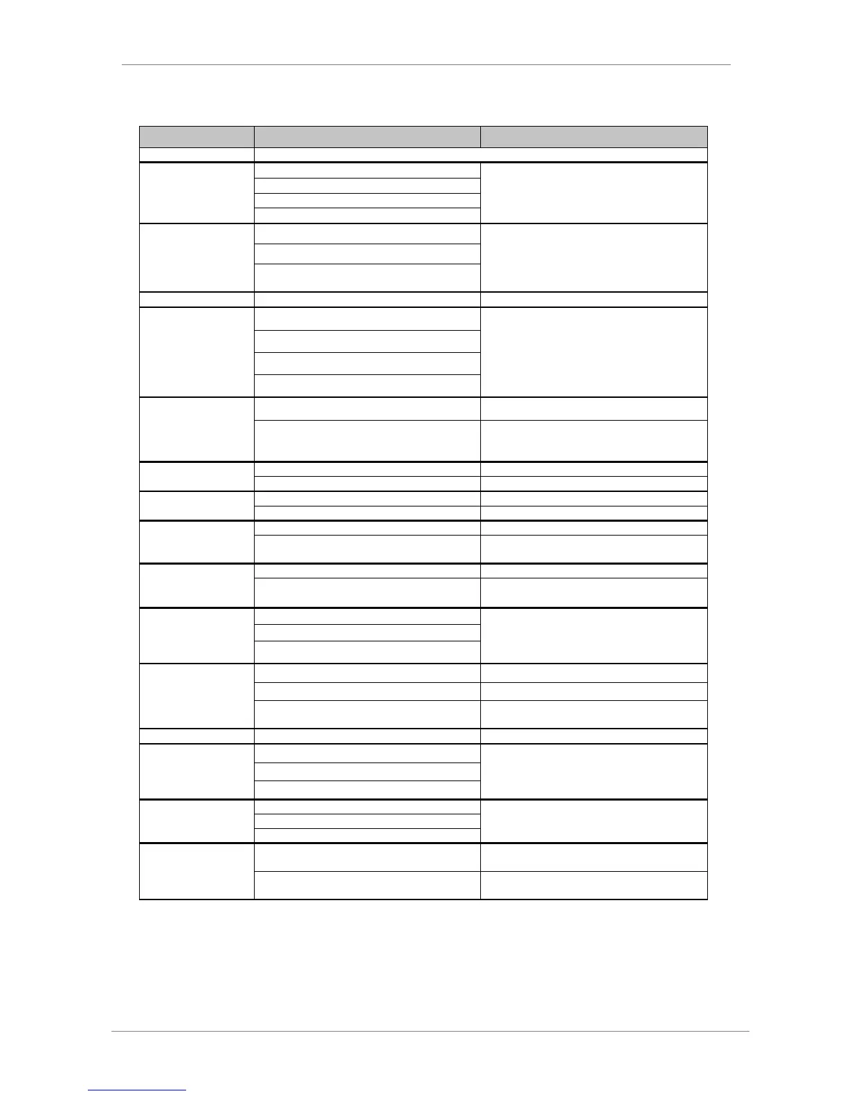
Drive is operative. There is no fault.
Motor output short circuit.
Check output cables and motor for possible wiring
faults or short circuits.
High voltage peak on the input.
Check conditions of input power supply.
Decrease deceleration ramps.
Deceleration ramp too high (parameters „G5.2
DECEL1‟ and „G5.4 DECEL2‟).
F4 OVERLOAD U+
F5 OVERLOAD U-
F6 OVERLOAD V+
F7 OVERLOAD V-
F8 OVERLOAD W+
F9 OVERLOAD W-
Check if there is possible wiring faults or a motor
fault. If the fault persists after disconnecting
output wires request technical assistance.
Extreme over current, equipment overload.
Wiring fault; circuit fault.
Desaturation of IGBT; IGBT fault.
See possible causes for faults F4 – F9.
Safe stop contact of the drive has been activated.
Revise the external circuit, where the safe stop
contact is connected, that produces the activation
of this contact into the drive.
Input power is incorrect, damaged fuses.
Check conditions of input power supply.
Input wiring is incorrect.
Input power is incorrect, damaged fuses.
Check conditions of input power supply.
Input wiring is incorrect.
Input power is incorrect.
Check input power conditions.
Incorrect setting of parameter „G11.6 HIGH
VOLT‟.
Check parameters settings.
Input power is incorrect, damaged fuses.
Check input power conditions.
Incorrect setting of parameter „G11.4 LOW
VOLT‟.
Check parameters settings.
Input power is incorrect.
Check input power conditions, load type of the
application, and all of the motor mechanical parts.
If the fault persists after disconnecting output
wires, request technical assistance.
Motor is driving an unstable load.
One of the input fuses is damaged.
High voltage peak on the input.
Check conditions of input power supply.
Check stop conditions of the drive.
Deceleration ramp too high (parameters „G5.2
DECEL1‟ and „G5.4 DECEL2‟).
Decrease deceleration ramps.
Input power is wrong, damaged fuses.
Check conditions of input power supply.
Motor is driving an unstable load.
Check motor circuit completely in case of possible
wiring faults or motor fault. If the fault persists
after disconnecting output wires, request
technical assistance.
Motor is supporting unstable loads.
Check motor circuit completely in case of possible
wiring faults or motor fault.
Motor or wiring has short-circuited to ground.
Disconnect the motor and wiring of the SD700FR
and check motor insulation.
Ground is incorrectly connected or wrong.
Check and improve the ground connection
system.