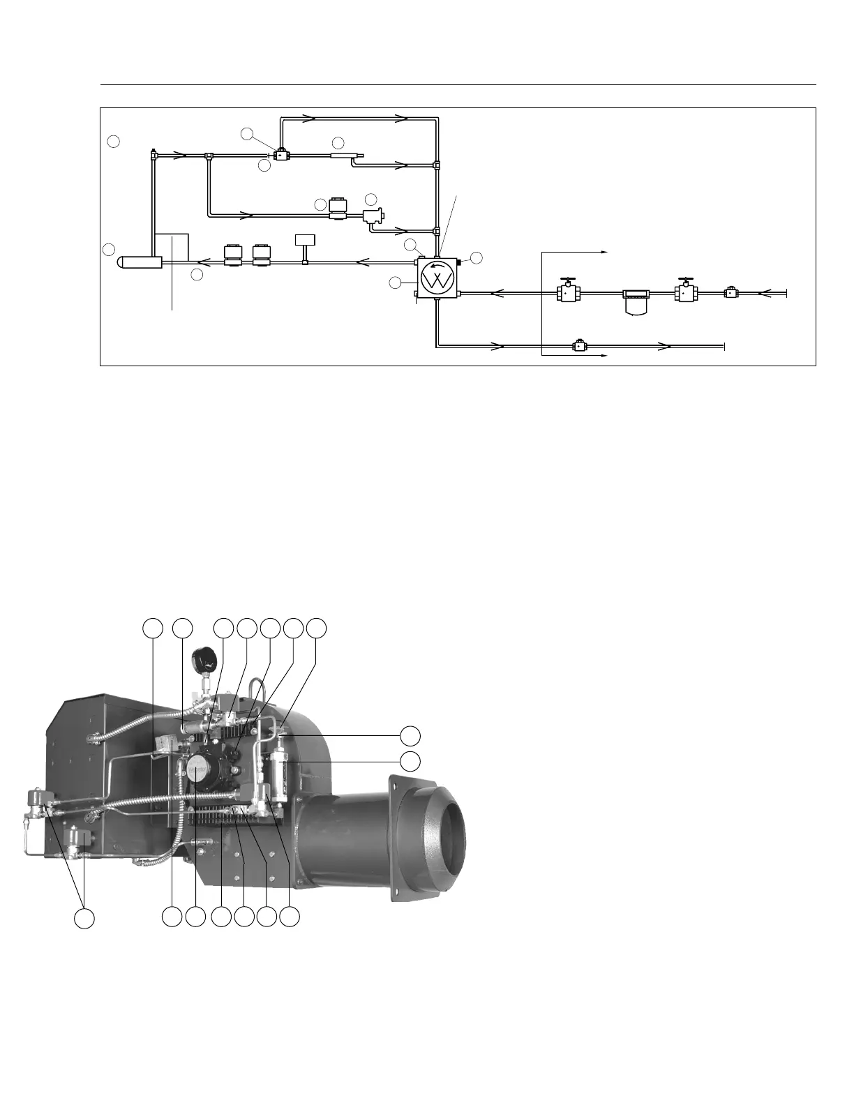
flow to the Nozzle. At the same instant a portion of the oil
bypasses the Nozzle through the adjustable low fire regulating
valve, reducing the pressure at the Nozzle as required for low
fire rates. When the low fire flame is proven by the flame
detector*, the Return Oil Solenoid Valve (7) is deenergized,
putting full high fire pump pressure on the Nozzle. Simulta-
neously, the Three-Way Solenoid Valve (10) is energized,
allowing oil into the Hydraulic Cylinder (9) which mechanically
drives the Air Damper Arm (13) to the high fire position. The
burner operates at full high fire until the system demand is
satisfied. Refer to page 31, Table 8 or page 34, Table 9 to
determine nozzle return flow pressure and flow rates. This
depiction shows the Air Dampers and Hydraulic Cylinder at the
low fire light off position.
The Low-High-Low system is identical to the Low-High-Off
system, except that an additional pressure or temperature
controller is added to the system, which at a selected preset
point will electrically switch the burner to either the high or low
fire position. When the burner is running at high fire and the
controller calls for low fire, the normally closed Oil Solenoid
Return Valve (7) (closed at high fire) is energized, reducing
nozzle pressure to the low fire rate. Simultaneously, the Three-
Way Solenoid Valve (10) is de-energized, allowing oil to flow
out of the Hydraulic Cylinder (9) back to the Pump and driving
the Air Dampers (4) to the low fire position. Responding to load
conditions, the burner can alternate indefinitely between the
low and high fire positions without shutting down. When system
load demand is satisfied, all fuel valves are de-energized and
the Air Dampers are placed in the light off position in prepara-
tion for the next firing cycle. The opening distance of the Air
Dampers is controlled by positioning the Air Damper Drive Arm
(13) relative to the Acorn Nut (16) mounted on the end of the
Hydraulic Cylinder piston rod. The maximum travel is with the
Damper Drive Arm positioned to be in contact with the hydraulic
oil cylinder Acorn Nut at all times. If less travel is desired, set the
Air Damper Drive Arm to allow a gap between it and the Acorn
Nut. (Depending on Air Damper positioning, it may be
necessary to loosen its set screws to attain proper Air Damper
opening distance.) The wider the gap (when the burner is off),
the less the overall travel when going to the high fire position.
When setting the Drive Arm position relative to the Acorn Nut,
make certain that the Air Dampers’ travel is correct for proper
combustion at all firing positions and that there is no binding
of the Linkage or Dampers. Make certain the cast iron Linkage
Return Weight (5) is secure on its Air Damper Arm (17).
* Not shown in this depiction. See page 4, Figure 2
Note 1
The system depicted in Figure 23 uses a Webster Model 22R oil
pump. If your system uses a Suntec H model pump, the sequence
14
Nozzle
1
Oil Solenoid
Valves
Field Piped
Low Oil
Pressure
Switch **
Oil Pump
2
Nozzle Port
Return Port
Inlet Port
Check Valve
(At Tank)*
Shutoff
Valve*
Fusible Link Valve
(If Required by Code)*
Filter*
Check
Valve*
Inlet
Return To
Tank
Field Piped
Pressure
Gauge Test Port
6
* By Others Unless Specified
on Order.
** Burners with Remote Pressure
Atomizing Oil Pumps require a
Low Oil Pressure Switch.
CAUTION:
All field piped components must be
mounted in the proper location
and proper direction of oil flow.
CAUTION:
Oil supply pressure to Burner
Pump must not exceed 3 PSI per
NFPA Code.
DO NOT USE TEFLON TAPE
15
Pressure
Tap
3 Way Oil
Valve
10
NO
C
NC
12
#72 Drill
Orifice
7
Return
Oil Valve
Low Fire
Regulating
Valve
9
Damper Cylinder
3
1
/
8
” Allen Screw
Under Cap For Oil
Nozzle Pressure
Adjustment
Vacuum Gauge
Inlet Port
Optional Return Port
For Simplex Nozzle Use Alternate
Connection to Tee on Outside of
Burner Instead of Connection to
Nozzle Adapter
Figure 23
Typical Oil Burner with Low-High-Off or Low-High-Low Fuel/Air Control Mode Using Webster 22R Oil Pump
8
C19
Rev.304
MECHANICAL OPERATION: This Low-High-Off system uses
a two-stage Oil Pump (2) with a Simplex Oil Nozzle (see
note 1, page 20) or an internal bypass nozzle in conjunction
with Movable Air Dampers (4) to provide a low fire start and
a high fire run sequence. A direct spark oil ignition system is
standard on typical oil burners (a gas pilot is standard on
Gas/Oil burners) at firing rates up to 45 GPH, with a spark
ignited gas pilot* to ignite the main oil flame above that
point. Certain insurance company codes could require the
gas pilot system on lower input sizes. Nozzle supply
pressure is set by adjusting the Oil Pump Pressure
Regulator (3). Turn clockwise to increase the pressure and
counter-clockwise to decrease the pressure to the Nozzle.
Nozzle supply pressure is taken at the plugged Pump
Nozzle Pressure Gauge Port (6). Nozzle supply pressure
will normally be approximately 300 PSI at both high and low
firing rates. Flow rate pressure for both high and low fire
is taken at Bypass Pressure Gauge Tee (15). Low fire
pressures are set by adjusting the low fire Regulating Valve
(8). Turning the low fire Regulating Valve adjustment nut
clockwise will increase the pressure at the Bypass Pressure
Test Tee Gauge (increasing the low fire input) and counter
clockwise will reduce the pressure at the gauge (decreasing
the low fire input). Low fire return pressure will normally be
in 60 to 100 PSI range and at high fire in the 180 to 225 PSI
range, but both pressures will vary according to the specific
nozzle being used, as well as job conditions. At light off, the
Main Oil Solenoid Valve (1) is energized, allowing fuel to
3617 8 1347
1
25
9
16
1015 12
4
 Loading...