of operation and the oil components would be identical to the
Webster 22R system. For additional information on your specific
system refer to the oil piping diagram and the oil pump
manufacturer’s bulletin supplied with the burner.
Note 2
Component operational sequencing will vary with the specific
Flame Safeguard Control being used. Refer to the specific
Flame Safeguard Control bulletin supplied with the burner for
complete information.
MECHANICAL OPERATION: This Low-High-Off system
uses a Two-Step Oil Pump with a Simplex Oil Nozzle (14)
in conjunction with movable Air Dampers (4) to provide
a low fire start and a high fire run sequence. A direct spark
oil ignition system is standard on typical Oil burners (a gas
pilot is standard on Gas/Oil burners), but certain insurance
company codes could require a spark ignited gas pilot*
to provide ignition for the main oil flame. Nozzle flow rate
pressure is taken at the
1
/
8
" Plugged Pump Pressure
Gauge Port (6). The low fire oil rate is set by adjusting the
Oil Pump Low Pressure Regulator (8). The high fire oil
flow rate is set by adjusting the Oil Pump High Pressure
Regulator (3). For both high and low fires turn the
adjustment screws clockwise to increase the pressure and
counterclockwise to decrease the pressure to the Nozzle.
Approximate low fire oil pressures are 100 to 125 psig
and high fire, 200 to 300 psig. Both settings will vary
depending upon the specific nozzle size selected and
job conditions. See pages 30-33, Tables 8 & 9 for specific
nozzle pressures and flow rates. At light off the Main Oil
Solenoid Valves (1) are energized, allowing fuel to the
Nozzle. A normally open pump mounted Oil Solenoid
Valve (7) allows a controlled flow of oil to the Nozzle in
accordance with the pressure setting of the pump low fire
14
Nozzle
1
Oil Solenoid
Valves
Low Oil Pressure
Switch **
Oil Pump
2
Nozzle Port
Return
Port
Inlet Port
Filter*
Inlet
Return
to Tank
Pressure Gauge Test Port
6
* By Others Unless Specified
on Order.
** Burners with Remote Pressure
Atomizing Oil Pumps require a
Low Oil Pressure Switch.
CAUTION:
All field piped components must be
mounted in the proper location and
proper direction of oil flow.
CAUTION:
Oil supply pressure to Burner Pump
must not exceed 3 PSI per NFPA
Code.
DO NOT USE TEFLON TAPE
3 Way Oil Valve
10
NO
C
NC
#72 Drill Orifice
7
N.O. Low Fire Solenoid
8
Flat Slot Screw-
driver Low Fire
Pressure Adjust-
ment
9
Damper Cylinder
3
Air Bleed
Valves
Optional
Inlet Ports
Oil
Pump
Side
View
Flat Slot
Screwdriver
High Fire
Pressure
Adjustment
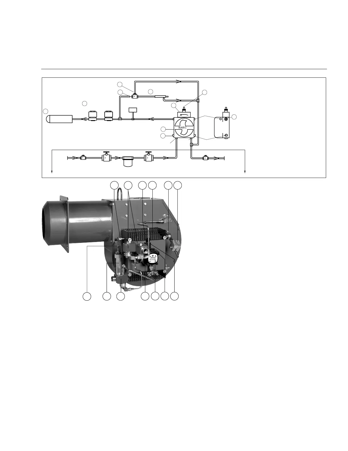
Figure 24
Typical Oil Burner with Low-High-Off or Low-High-Low Fuel/Air Control Mode Using a Two-Step Oil Pump (Model C-O)
Field Piped
Check Valve
(At Tank)*
Fuel
Shutoff
Valve*
Fusible Link Valve
(If Required by Code)*
Check
Valve*
Field
Piped
12
adjustment. When the low fire flame is proven by the
flame detector*, the pump mounted, normally open
Solenoid Valve is energized (closes), putting full high
fire pump pressure on the nozzle. Simultaneously, the
Three-Way Solenoid Valve (10) is energized, allowing
oil into the Hydraulic Oil Cylinder (9) which mechanically
drives the Air Damper Arm (13) to the high fire open
position. The burner operates at full high fire until the
system demand is satisfied. This depiction shows the Air
Dampers and the Hydraulic Cylinder at the low fire light
off position.
The Low-High-Low systems are identical to the Low-High-
Off system, except that an additional temperature or
pressure controller is added to the system. At a selected
preset point, it will electrically switch the Oil Valves and
Air Damper components to place the firing rate either in
the low or the high fire run position. When the burner is
running at high fire and the controller calls for low fire, the
normally open pump mounted Solenoid Valve (7) (which
is closed at high fire) is de-energized (opens), reducing
nozzle pressure to the low fire rate. Simultaneously, the
Three-Way Solenoid Valve (10) is de-energized, allowing
oil to flow out of the Hydraulic Cylinder back to the Pump
(2) and driving the Air Dampers (4) to the low fire position.
Depending on load conditions, the burner can alternate
indefinitely between the low and the high fire positions
without shutting down. When system demand is satisfied
all fuel valves are de-energized and the Air Dampers are
placed in the light off position for the next start up. The
Air Damper position for low fire run and light off position
are one and the same in this system. The opening
distance of the Air Dampers is controlled by positioning
the Air Damper Drive Arm (13) relative to the Acorn Nut
(16) mounted on the end of the Hydraulic Cylinder (9)
piston rod. The maximum travel is with the Damper Drive
Arm positioned to be in contact with the hydraulic oil
cylinder Acorn Nut at all times. If less travel is desired, set
the Air Damper Drive Arm to allow a gap between it and
the Acorn Nut. (Depending on Air Damper positioning, it
may be necessary to loosen its set screws to attain proper
Air Damper opening distance.) The wider the gap (when
the burner is off), the less the overall travel when going
to high fire position. When setting the Drive Arm position
relative to the Acorn Nut, make certain that the Air Damper
travel is correct for proper combustion at all firing positions
10
13
316
1
9
7 4 17 15
2
6 8
C20
Rev.304