Installation
37
Powerware
®
9125 User’s Guide (2500–3000 VA) : Rev B www.powerware.com
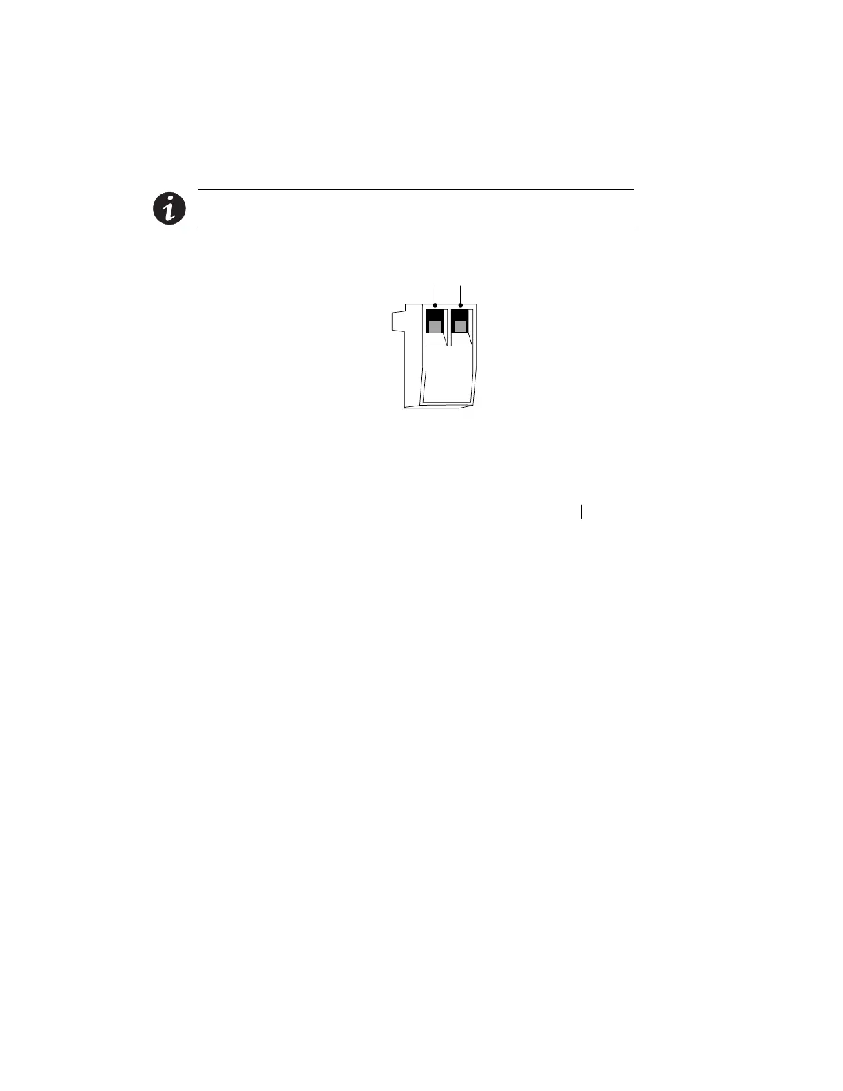
3. Connect isolated, normally-closed, dry contacts (rated to
handle 60 Vdc maximum, 30 Vac RMS maximum, and 20 mA
maximum) across the REPO device to Pin 1 and Pin 2 (see
Figure 21). Use stranded, non-shielded wiring, size
18–22AWG(0.75mm
2
–0 mm
2
).
NOTE A separate contact must simultaneously cause UPS input AC power to be
removed.
4. Reconnect the REPO connector to the REPO port.
Pin 1 Pin 2
Figure 21. REPO Connector
5. Verify that the externally-connected REPO switch is not
activated to enable power to the UPS output receptacles.
6. Plug in the UPS (or switch the main utility breaker on for
hardwired units) and start the UPS by pressing the On
button.
7. Activate the external REPO switch to test the REPO function.
8. De-activate the external REPO switch and restart the UPS.