Installation
38
Powerware
®
9125 User’s Guide (2500–3000 VA) : Rev B www.powerware.com
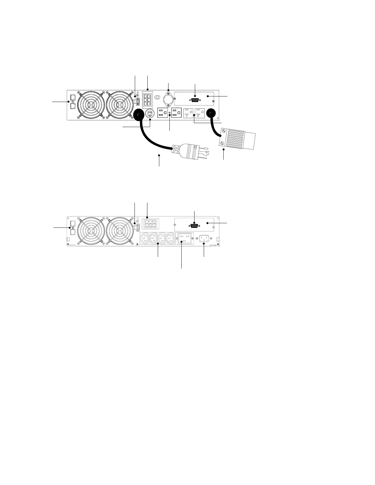
UPS Rear Panels
This section shows the rear panels of the Powerware 9125 models.
REPO Port
Two 5-15 Receptacles
Battery Connector
Power Cord with 5-30P
Communication Port
Network
Transient
Protector
X-Slot
5-30 Receptacle
Two 5-20 Receptacles
Fuse Holder
Circuit Protector
Figure 22. 2500/3000 VA, 120V Rear Panel
Four 10A, IEC 320-C13 Receptacles 16A, IEC-320 Input Connector
REPO Port Battery Connector
Communication Port
Network
Transient
Protector
X-Slot
16A, IEC 320-C19 Receptacle
Figure 23. 2500/3000 VA, 208V Rear Panel