Installation
30
Powerware
®
9125 User’s Guide (2500–3000 VA) : Rev B www.powerware.com
Plug-Receptacle UPS Installation
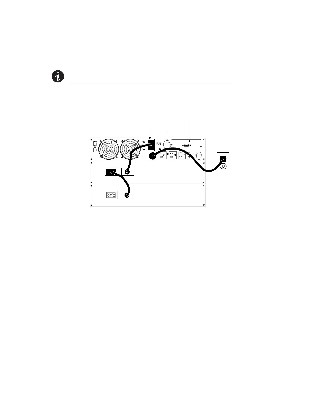
The following steps explain how to install the UPS. Figure 15 shows a
typical installation only. See “UPS Rear Panels” on page 38 for the rear
panel of each model.
NOTE Do not make unauthorized changes to the UPS; otherwise, damage may occur
to your equipment and void your warranty.
1. If you are installing power management software, connect your
computer to the UPS communication port using the supplied
communication cable.
UPS Battery Connector
Power Cord
Output
Receptacles
Communication Port
Figure 15. Typical UPS Installation (120V Model Shown)
2. Plug the equipment to be protected into the appropriate UPS
output receptacles (see page 55 for more information on load
segments).
DO NOT protect laser printers with the UPS because of the
exceptionally high power requirements of the heating elements.
3. If an emergency power-off (disconnect) switch is required by
local codes, see “Remote Emergency Power-Off” on page 36 to
install the REPO switch before powering on the UPS.