AR Standard Repeater Sub Unit Overview
1-4 044-05250 Rev B
connected to Fiber Optic Repeaters (FORs) and WRHs by using WDMs and splitters. FORs
and WRHs can be fed in parallel with double or single fiber optic cables. Up to eight FORs and
WRHs can be fed if the BMU is equipped with a high cover and two FONs. The BMU is also
available as a 19" rack mounted unit called an Optical Conversion Module (OCM). Information
on the OCM is located in the Fiber Optic Equipment User Manual (044-052530).
Repeater Master Unit (RMU)
An RMU is a repeater equipped with a FON for optical transmission on the service side. The
RMU has an RF port for a donor antenna and provide up to four fiber optic ports that can be
connected to FORs and WRHs by using WDMs and splitters. FORs and WRHs can be fed in
parallel with double or single fiber optic cables. Up to eight FORs and WRHs can be fed if the
BMU is equipped with a high cover and two FONs.
Fiber Optic Repeater (FOR)
A FOR is a repeater equipped with a FOU for optical transmission on the donor side. The FOR
can connect to either a service antenna or RF cable. The FOR has a fiber optic donor port and
an RF port for a service antenna (or RF cable). This unit can be connected to a BMU or RMU.
Combined Repeater
Some of the repeater types mentioned above can be combined in the same repeater chassis
and be in operation in parallel. This can be used for different systems or different operators.
One repeater part is located in the cabinet and an additional repeater part is located in a high
cover. A combined repeater can, for example, have two RF ports for donor antennas (or RF
cables) and two RF ports for service antennas (or RF cables).
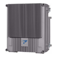
Repeater Chassis Design
The repeater is housed in a cast aluminium waterproof chassis, class NEMA4 / IP65 approved
for outdoor use but is also suited for indoor installations. The chassis consists of a cabinet and
a cover attached with hinges. The cabinet contains the repeater circuitry. The cover comes as
either a low or high version. The high cover can be used as an empty cover or be equipped as
a part of the repeater or an independent repeater unit. A repeater with a high cover that is
equipped as two independent repeater units (combined repeater) can, for example, be
equipped for channel selective operation in the cabinet and band selective operation in the
cover.
Sub Unit Overview
A number of amplifier boards are individually shielded and located under a metal cover inside
the repeater. This cover can be opened outward for access. These amplifier PCBAs are of
different types depending on the supported system. All of the repeater types are built up with
a number of sub units which are described in the following paragraphs.
Channel Amplifier PCBA for GSM and EDGE (CHE)
The CHE is used for CSel operations. CSel GSM repeaters can handle up to eight channels.
For every even number of channels, two CHEs are required, one for the uplink and one for the
downlink. Numbered from left to right, positions 1 and 2 are used for two DL CHEs and 3 and
4 for two UL CHEs. Each repeater channel is allocated to a radio channel or switched off. In a
GSM system, each repeater channel can handle eight calls (sixteen if half-rate encoding is
used).
CDMA/WCDMA Segment Amplifier PCBA (CSA)
CSel CDMA/WCDMA repeaters can handle two CDMA or WCDMA repeater channels. The
CSA provides this capability. For every even number of channels, two CSAs and two PAs are
required; one pair of CSA/PAs for the uplink and one pair for the downlink. Each repeater
channel is allocated to a radio channel or switched off. Numbered from left to right, position 1
is used for a CSA, position 2 for a DL PA, position 3 for a CSA and position 4 for a UL PA.