Connections AR Standard Repeater
3-8 044-05250 Rev B
FOR RF to Fiber Optic Connections
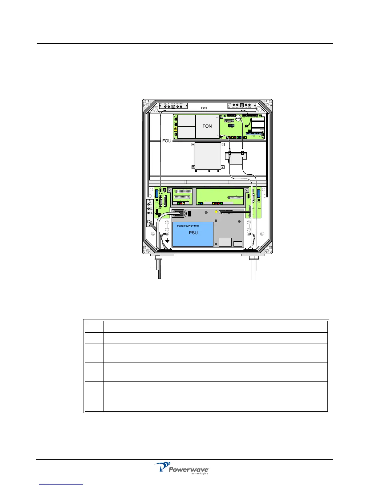
Figure 3-9 illustrates a FOR for service antenna and separate TX/RX fiber optic cables from a
BMU. By adding WDMs and OSPs, a number of FORs can be fed by one BMU with double or
single fiber communication. Table 3-4 describes the steps for making the connections.
Figure 3-9 FOR RF-to-Fiber Optic Connections
Table 3-4 FOR RF-to-Fiber Connections Procedure
Step Action
1 Mount AR Repeater
2
Connect the service antenna coaxial cable to the left in the cabinet using an N-
type male connector.
3
Connect the TX and RX fiber optic cables from the BMU to the FON located in
the upper part of the FOU
4 Connect station ground, if to be used
5
Mount the main power plug to the main power cord but do not connect the main
power.
MS
DPX
ANT
TEST
DC
-30 dB
-20 dB
POWER SUPPLY UNIT
ALLGON INNOVATION
SWEDEN M105 R6
1
PARKING
FOR W5
W5
8
P27
W6B 10
1
P33
ALAR M
P23
LNA
UP-LINK
P32
MODEM
A
U
X
1
P28
DOOR
5
9
6
1
1
16
1
1
M
-
>
S
P11
P34
8
9
15
P26
15 16
S
-
>
M
1
2
3
89
P
3
6
5
X0A
X0B
2
V2
1
16
P12 P13
1
1
1
16
16
16
P4
P5
P6
c
b
a
c
b
a
c
b
a
c
b
a
1P232
1
b
a
1
16P3
16
1
16
P14
1
V1
1
1
1
1
1
4
6
1
15
6
9
15
2
16
1
2
4
5
8
5
P35
P21
PSU
6
10
P31
PC
P29
P24
P25
GND
7
6V6
LNA
DOWN-LINK
LED
P22
1
2
TX
OUT
LOWIN+ 7V ATTOUT2 OUT1
LNA
DL
OUT
LOW
IN ATT +7V OUT1 OUT2
LNA
UL
RX
FOU
PSU
R2R
P102
P130
Beryllium
oxide
hazar d
P103
P101
P114
P108P116P111
P105P109P115
P106
P104
RX
TX
P113
P112
P110
FON
BMU