Sub Unit Locations AR Standard Repeater
044-05250 Rev B 1-7
Repeater-to-Repeater Interface Adapter (RIA)
The RIA is required for R2R networking if a previous CU PCBA (K103/2), is used. This PCBA
is located in the upper left part of the shielded DIA frame. R2R functionality is included starting
in the CU PCBA part # K103/3.
Sub Unit Locations
The following sections describe the sub unit locations of the different models of AR Repeater
and distribution units.
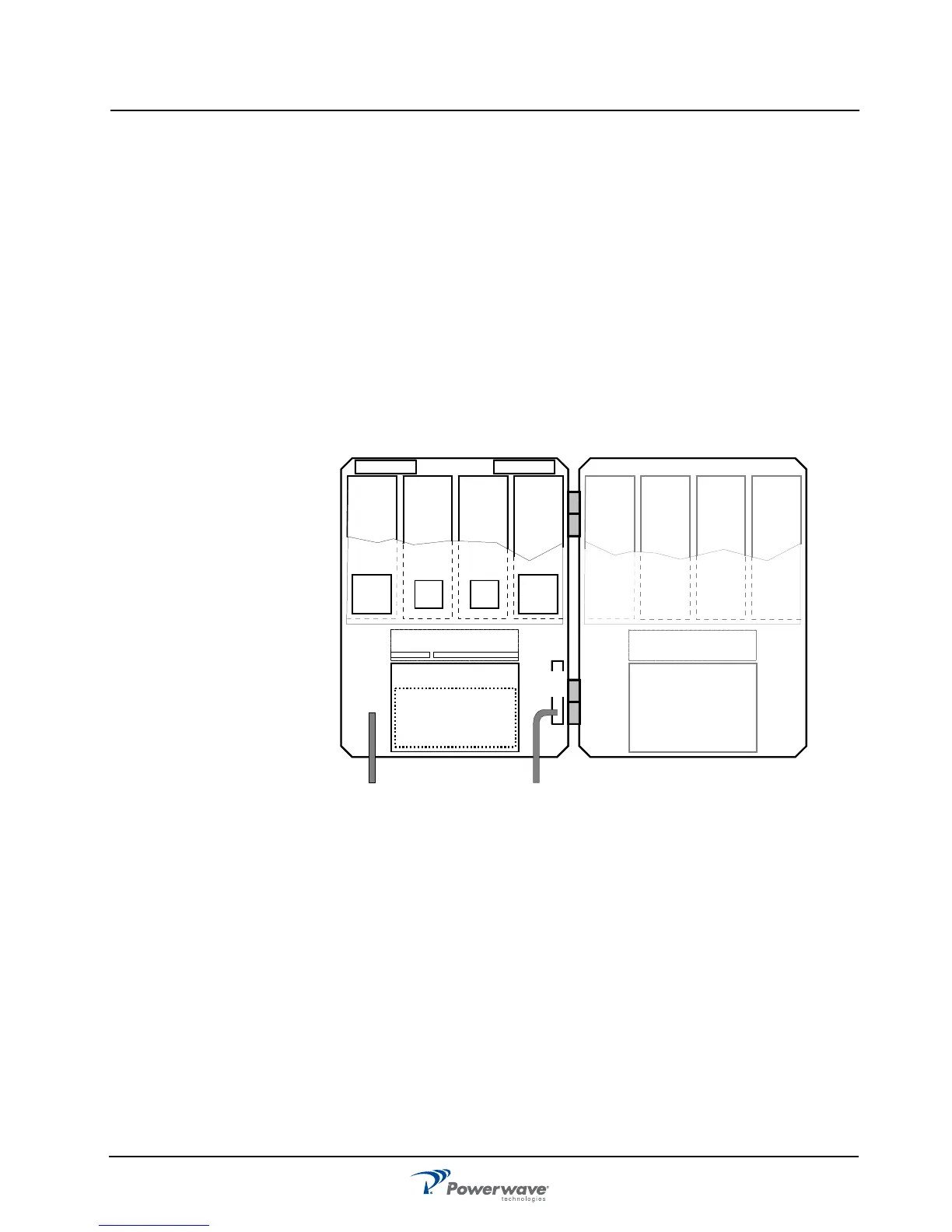
CSel GSM Repeater
A cabinet for a CSel GSM repeater can be equipped with four CHEs, two for the downlink (DL)
with two internal channels each and two for the uplink (UL) with two internal channels each.
The described cabinet has a capacity of four bi-directional GSM channels. A high cover can be
equipped as well providing up to eight GSM channels. PCBA positions are illustrated in
Figure 1-3 and a block diagram is located in Appendix A.
Figure 1-3 CSel GSM Repeater Sub Unit Locations
CSel CDMA/WCDMA Repeater
A cabinet for a CSel CDMA or WCDMA repeater can be equipped with two pair of CSAs and
PAs, one pair for the DL and one pair for the UL. The described cabinet has a capacity of two
bi-directional CDMA or WCDMA carriers. A high cover can be equipped as well providing up
to four CDMA or WCDMA channels. PCBA positions are illustrated in Figure 1-4 and a block
diagram is located in Appendix A.
LNA - DL
1234
LNA - UL
PSU
(RCU)
DPX
CUALI/RCI
DC
BS
DPX
CHA1
DL
2
CHA2
DL
2
CHA3
UL
2
CHA4
UL
2
CMB
DL
CMB
UL
1234
CHA1
DL
2
CHA2
DL
2
CHA3
UL
2
CHA4
UL
2
5678
CHA5
DL
2
CHA6
DL
2
CHA7
UL
2
CHA8
UL
2
PSU