AR Standard Repeater PCBA Connections
2-12 044-05250 Rev B
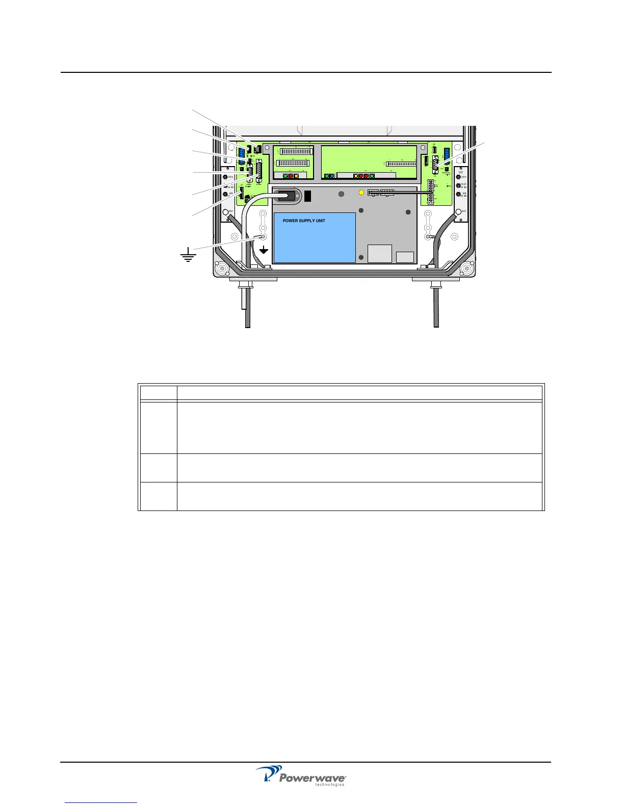
Figure 2-8 Power Supply Unit (PSU)
Table 2-13 PSU Connectors
Port Description
P27 Auxiliary Port (8-pin male) - Used to power the old RCU. It is located on the DIA
to the left in the cabinet. Pins 2 and 3 must always be interconnected to provide
the CU and ALI/RCI PCBs with voltage supply. If there is no cable connected,
pins 2 and 3 must be interconnected with a jumper.
P31 RS-232 PC Port (9-pin D-sub female) - Used for local PC communication. It is
located on the DIA to the right in the cabinet.
P32 RS-232 Modem port (9-pin D-sub male) - V.24 interface used for the old RCU.
It is located on the DIA to the left in the cabinet.
MS
DPX
ANT
TEST
DC
-30 dB
-20 dB
MS
DPX
ANT
TEST
DC
-30 dB
-20 dB
POWER SUPPLY UNIT
AL LGON INNOVATI ON
SWEDEN M105 R6
1
PARKI NG
FOR W5
W5
8
P27
W6B 10
1
P33
ALARM
P23
LNA
UP-LINK
P32
MODEM
A
U
X
1
P28
DOOR
5
9
6
1
1
16
1
1
M
-
>
S
P11
P34
8
9
15
P26
15 16
S
-
>
M
1
2
3
89
P
3
6
5
X0A
X0B
2
V2
1
16
P12 P13
1
1
1
16
16
16
P4
P5
P6
c
b
a
c
b
a
c
b
a
c
b
a
1P232
1
b
a
1
16P3
16
1
16
P14
1
V1
1
1
1
1
1
4
6
1
15
6
9
15
2
16
1
2
4
5
8
5
P35
P21
PSU
6
10
P31
PC
P29
P24
P25
GND
7
6V6
LNA
DOWN- LINK
LED
P22
1
2
P33
P27
P31
P32
P34
P28
P36