Connections AR Standard Repeater
3-6 044-05250 Rev B
BMU RF to Fiber Optic Connections
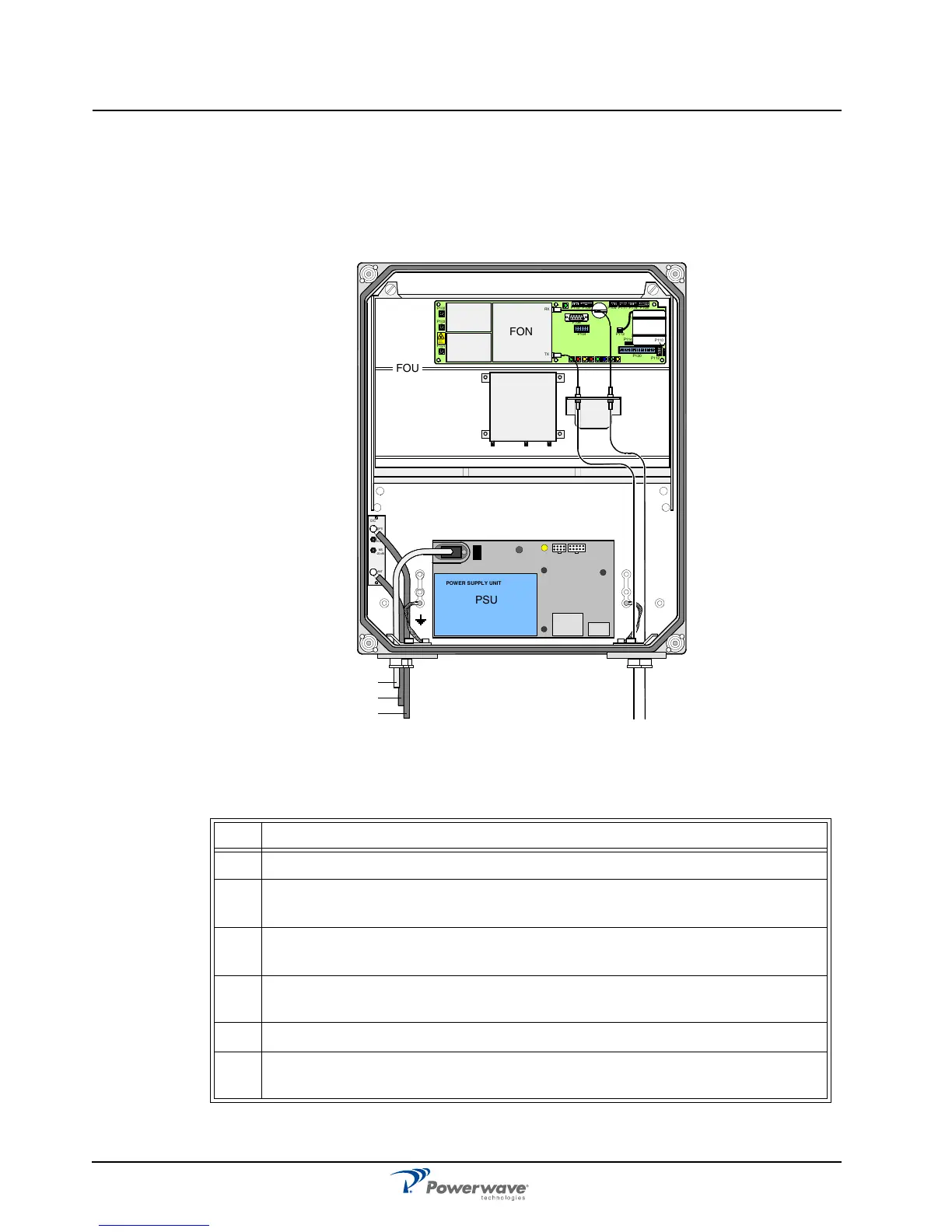
Figure 3-7 illustrates a BMU with separate TX/RX fiber optic cables to one FOR. By using
WDMs and OSPs, up to four FORs, or eight using a high cover, can be fed in parallel by one
BMU with double or single fiber optic cables. Table 3-2 describes the steps for making the
connections.
Figure 3-7 BMU RF-to-Fiber Optic Connections
Table 3-2 BMU RF-to-Fiber Connections Procedure
Step Action
1 Mount AR Repeater
2
Using N-type male connectors, connect the BTS antenna output RF cable to the
ANT port of the DC unit located on the left in the cabinet.
3
Connect an RF cable from the DPX port of the DC unit located on the left to the
BTS antenna using an N-type male connector
4 Connect the TX and RX fiber optic cables from the FON located in the upper part
of the FOU to a FOR.
5 Connect station ground, if to be used
6
Mount the main power plug to the main power cord but do not connect the main
power.
MS
DPX
ANT
TEST
DC
-30 dB
-20 dB
POWER SUPPLY UNIT
FOU
TX RX
PSU
P102
P130
Beryllium
oxide
hazar d
P103
P101
P114
P108P116P111
P105P109P115
P106
P104
RX
TX
P113
P112
P110
FON
BTS
FOR