AR Standard Repeater Sub Unit Locations
1-10 044-05250 Rev B
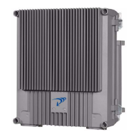
Figure 1-8 Optical Converter Module (OCM)
RMU
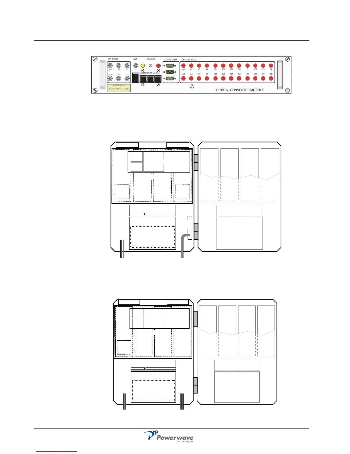
Figure 1-9 illustrates an example of an RMU for BSel operation. This unit has a FON and a
DPX. By adding WDMs and splitters to the FOU up to four FORs can be fed in parallel by a
BMU with double or single fiber communication. A block diagram is located in Appendix A.
Figure 1-9 RMU Sub Unit Locations
FOR
Figure 1-10 illustrates an example of a FOR for band selective operation. This unit has a FON
and a DPX.
Figure 1-10 FOR Sub Unit Locations
LNA - DL
1234
LNA - UL
PSU
(RCU)
DPX
CUALI/RCI
DC
BS
DPX
BSA
DL
PA
DL
BSA
UL
PA
UL
5678
PSU
BSA
DL
PA
DL
BSA
UL
PA
UL
FOU
FON
LNA - DL
1234
LNA - UL
PSU
(RCU)
DPX
CUALI/RCI
BSA
DL
PA
DL
BSA
UL
PA
UL
5678
PSU
BSA
DL
PA
DL
BSA
UL
PA
UL
FOU
FON