PCBA Connections AR Standard Repeater
044-05250 Rev B 2-9
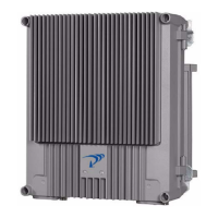
Figure 2-6 FOU
Table 2-10 FOU/DPX connections
FON
The FON is illustrated in Figure 2-7 and the LED indicators are described in Table 2-11. The
FON has three coaxial ports and two optical ports for the downlink and uplink RF signal. Table
2-12 defines the port numbers, connector types, and port usage.
on the donor side (BMU or RMU)
Port Connected to
ANT BMU: BS -20dB on the donor (BS) DC
RMU: DPX on the donor (BS) DC
HI BMU: P101 on the FON (or a CMB or CMD)
RMU: IN on the LNA/DL
LO BMU: P102 on the FON (or a CMB or CMD)
RMU: P5 on the PA/UL
on the service side (FOR and WRH)
Port Connected to
ANT Service antenna
HI FOR: P5 on the PA/DL
WRH: P5 on the PA/DL or P4 on the BA
LO FOR: IN on the LNA/UL
WRH: IN on the LNA/UL or P2 101 on the WBA
P102
P130
Beryllium
oxide
hazard
P103
P101
P114
P108P116P111
P105P109P115
P106
P104
RX
TX
P113
P112
P110
FON
DPX
ANTLO HI
P102
P101
FOU