AR Standard Repeater PCBA Connections
2-6 044-05250 Rev B
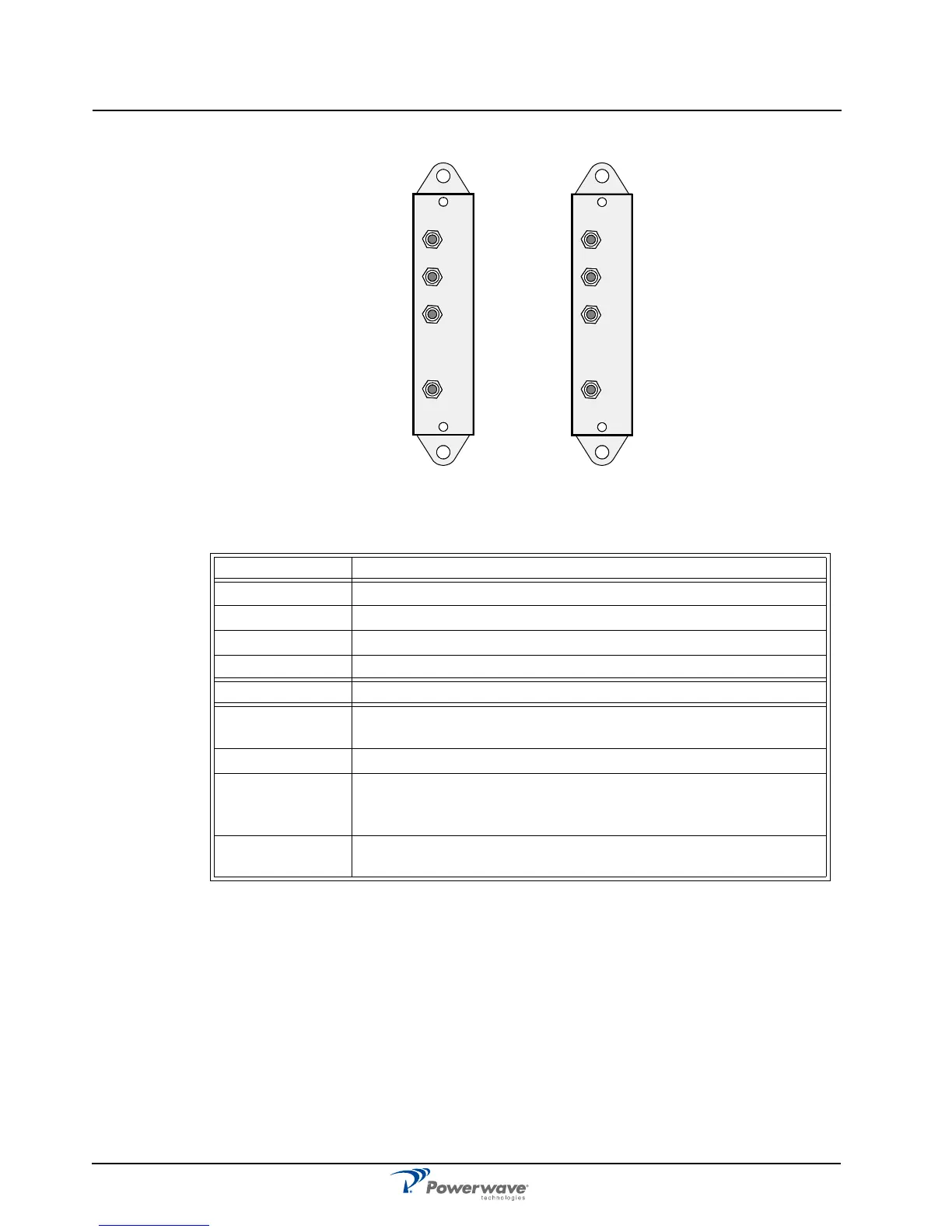
Figure 2-4 Directional Couplers
Table 2-7 Directional Coupler Connections
LNA
Figure 2-5 illustrates the LNA and Table 2-8 lists the connectors and connections. All coaxial
connectors are SMA-type. Signals from the DPX output are fed to the LNA input connector
IN. OUT1 and OUT2 outputs feed the CHE, CSA or BSA of the same signal direction.
The signal level in these connectors are +20dB referenced to the antenna input. OUT LOW is
an expansion output for an additional LNA if the repeater is equipped in a high cover. The
gain to this connector is +2dB. The +7V input is used for +7V supply from the DIA PCBA and
ATT is a control signal for a controllable attenuator in the LNA.
Service DC Port Connected to
DPX ANT on the service DPX filter
TEST -30dB Test port for the downlink output signal (no directivity)
MS -20dB Not used
ANT Service antenna or RF service cable
Donor DC Port Connected to
DPX BMU: BTS antenna
All other types: ANT on the donor DPX duplex filter
TEST -30dB Test port for the uplink output signal (no directivity)
BS -20dB BMU: ANT on the FOU/DPX filter
All other types: Antenna connection for remote control RF modem.
This port has at least 20dB directivity towards the antenna.
ANT BMU: BTS antenna output port.
All other types: Donor antenna (or RF cable to BTS).
MS
DPX
ANT
TEST
DC
-30 dB
-20 dB
BS
DPX
ANT
TEST
DC
-30 dB
-20 dB