AR Standard Repeater Connections
044-05250 Rev B 3-5
This AC version of this product is also designed to be able to use IT power systems with
phase to phase voltage (230 V). the power connection should be protected with a 20 A
breaker. Over current and short current protection also relies on building installation.
RF-to-RF Repeater Connections
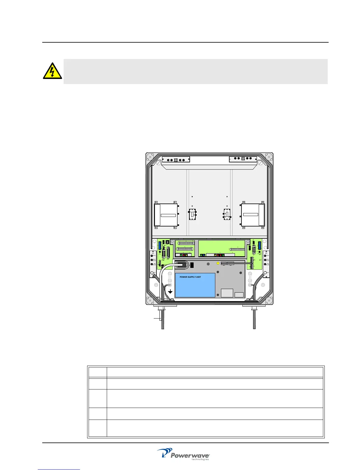
Figure 3-6 illustrates the cable connections applicable for standard and high power repeaters
and Table 3-1 describes the steps for making the connections. The donor antenna or RF
cable from the BTS is connected to the right and the service antenna is connected to the left
in the cabinet.
Figure 3-6 RF-to-RF Repeater Connections
Table 3-1 RF-to-RF Connections Procedure
WARNING: Prior to applying power to an AC repeater, verify that the AC voltage selection
switch, located to the right of the power plug recepticle, is set to the appropriate voltage
level (115 VAC or 230 VAC). An incorrect setting may damage the equipment.
Step Action
1 Mount AR Repeater
2
Using N-type male connectors, connect the service and donor antenna coaxial
cables (or RF cable from the BTS if no donor antenna is used).
3
Verify that the connector ports are tagged as such.
4 Connect station ground, if to be used, and mount the main power plug to the
main power cord but do not connect the main power.
MS
DPX
ANT
TEST
DC
-30 dB
-20 dB
MS
DPX
ANT
TEST
DC
-30 dB
-20 dB
POWER SUPPLY UNIT
ALLGON INN OVATION
SWEDEN M105 R6
1
PARKING
FOR W5
W5
8
P27
W6B 10
1
P33
ALAR M
P23
LNA
UP-LINK
P32
MODEM
A
U
X
1
P28
DOOR
5
9
6
1
1
16
1
1
M
-
>
S
P11
P34
8
9
15
P26
15 16
S
-
>
M
1
2
3
89
P
3
6
5
X0A
X0B
2
V2
1
16
P12 P13
1
1
1
16
16
16P4
P5
P6
c
b
a
c
b
a
c
b
a
c
b
a
1P232
1
b
a
1
16P3
16
1
16
P14
1
V1
1
1
1
1
1
4
6
1
15
6
9
15
2
16
1
2
4
5
8
5
P35
P21
PSU
6
10
P31
PC
P29
P24
P25
GND
7
6V6
LNA
DOWN-LINK
LED
P22
1
2
OUT
LOW
IN+7V AT TOUT2 OUT1
LNA
DL
OUT
LOW
IN ATT +7V OUT1 OUT2
LNA
UL
PSU
Service Donor