Premier Tech 15 / 64 Solido SMART
DOKK5110E 15.04.2020
4.3 General
The Solido SMART small wastewater treatment plant combines all of the benefits of the
trusted SOLIDO technology in an extremely compact space. The SBR procedure used works
in a similar way to a municipal treatment plant - by directly aerating the incoming wastewater
without a preliminary treatment chamber.
This ensures very effective wastewater purification and prevents the build-up of harmful
biogases.
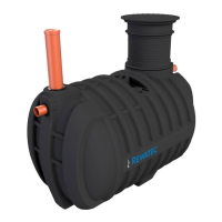
The Solido SMART small wastewater treatment plant is shown with the BL container in the
following figure.
The volume and shape of the container for your small wastewater treatment plant may differ,
but the functional principle shown here is the same.
4.4 Treatment process with the Solido SMART
The Solido SMART SBR small wastewater treatment plant is comprised of highly resistant
polyethylene plastic containers and works as a sequencing batch reactor. It is available in a
variety of versions for different numbers of users (referred to in the text below as inhabitants).
The special feature of the plant design is that all mechanical coarse material separation and
pretreatment is dispensed with. All primary and secondary sludge is aerobically treated in
one chamber.
The simultaneous aerobic sludge stabilisation leads to a significant reduction in sludge
accumulation and unwelcome odours in comparison to SBR plant designs with two stages
Using a time-controlled twelve-hour SBR cycle (intermittent aeration, sedimentation,
discharge of clearwater), the same multi-purpose chamber is used as a reactor, sludge
reservoir, and buffer.
As a result, the whole volume benefits from practically the full scope of relevant functions at
the various cycle times.
All of the process cycles are performed by an electronic controller that includes an operating
hour meter, a logbook function, visual and audible warning signals to indicate faulty hydraulic
or electrical functions and a mains-independent power failure monitoring system. An overfill
alarm is provided using sensors (float switches) in the container.