3 Installation
The i4 Spot Welder requires one of the following voltage / frequency combina-
tions:
208-240V 50/60 Hz U.S.A., Canada, Japan OR
400-420V 50/60 Hz Europe, Australia
Note: Make sure that the facility supply voltage and frequency are the same as
shown on the welder name plate (see section 4.2 “About your welder”).
The power supply must have a ground connection. The supply must also be
protected as follows:
The 208-240V 3-Phase or Single-Phase require 60A breaker.
The 400V and 420V supply require a 32A slow blow fuse (Circuit
breaker 32D).
WARNING! All electrical connections must be made by a qualified
electrician. Risk for electrical shock.
1. Connect the green wire to ground.
Note: Make sure that the supply cable is at least 6 AWG at 208V and 400 V.
The i4 is rated for over voltage category III and polution degree 3.
2. If an extension cord is used with the welder, ensure that the length of the
extension cord does not exceed 10 m (30 ft) and it meets the specifications of
Item 1 above. The cord must also be grounded. Consult
an electrician for safe and proper installation of the electrical plug.
NOTE: When connecting the welder to Single-Phase input power, install Red and
White wires. Connect Green to earth ground! Leave out the black wire. Insulate
and store the black wire properly.
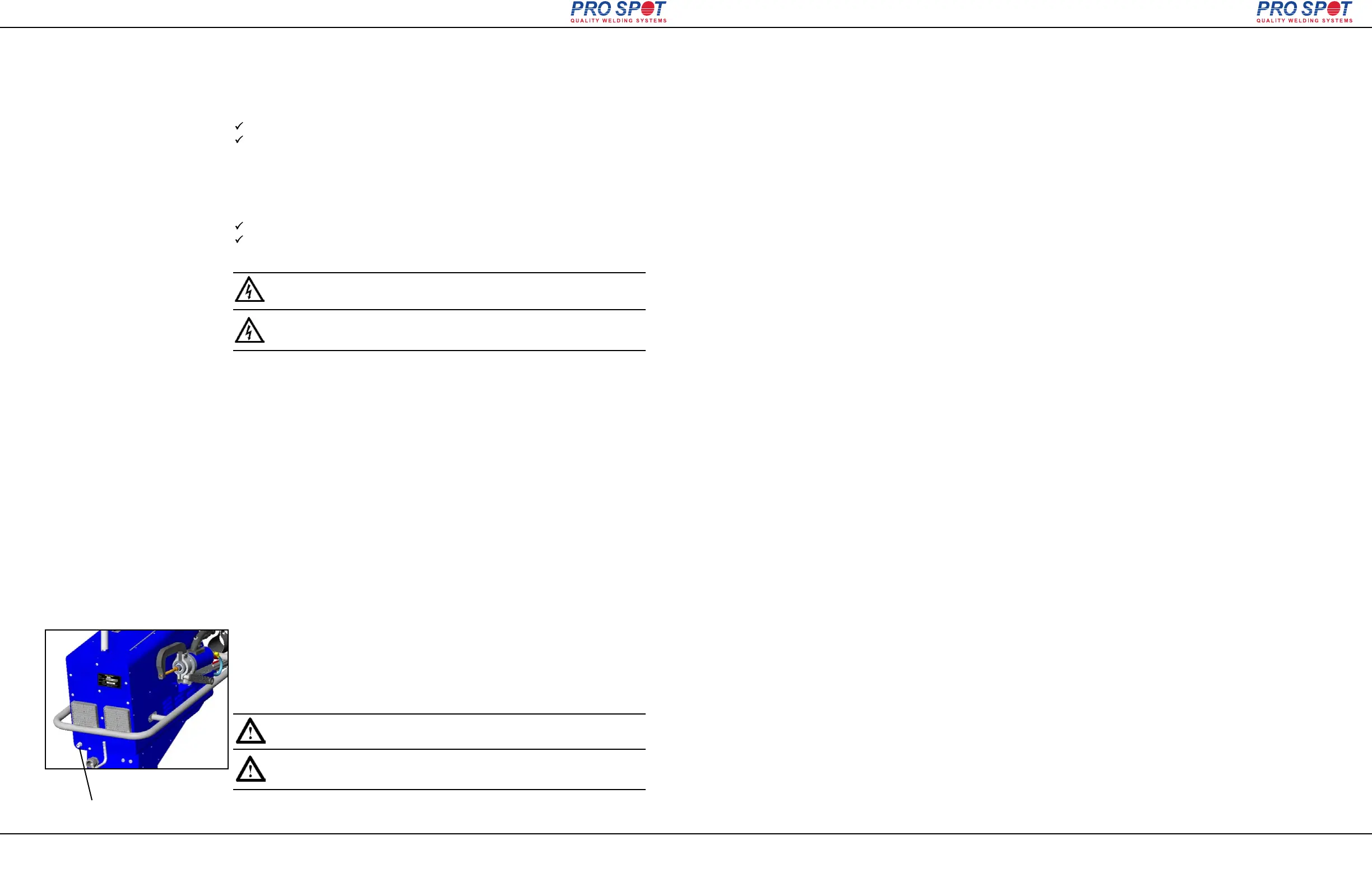
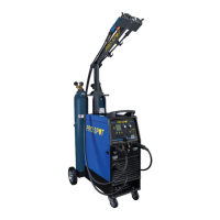
Air supply port
The i4 Spot welder must be connected to a pneumatic air network.
(100 PSI to 130 PSI)
1. Connect the i4 to the air supply via the threaded input port at
the rear of the welder using a standard connector.
2. If not already set, adjust the air pressure setting on the welder front panel to
60 PSI (4-5 bar) (refer to section 4.5 “Setting the pneumatic air pressure”).
IMPORTANT! The air must be clean and free from oil and
moisture. Use a filter.
Figure 3.2
Page 9
All Info Copyright © Pro Spot International Inc.
3.5 Connection of pneumatic air supply
3.4.1 Electrical Plug / Extension cords
3.4 Connection of electrical supply
i4
ATTENTION! Toutes les connexions électriques doivent être
faites par un électricien qualifié . Risque de choc électrique.
IMPORTANT! L'air doit être propre sans huile et
humidité. Utilisez un filtre.
4 Operation
Before you begin welding, be sure to read and understand the following instruc-
tions.
The Pro Spot i4 is a state-of-the-art Inverter Resistance Spot Welder that was
designed for the collision repair industry. It duplicates the welding procedure used
by the car manufacturers. It is important to understand the design and function of
this welder before operating it.
ELECTRICITY ONLY: The i4 uses only electricity to create the welds unlike the
MIG welder which uses an arc from a feeding wire to build a weld nugget using
inert gas and the feeding wire material.
PRESSURE: The i4 has a built in air cylinder that compresses the Double-Sided
Gun’s welding tips together automatically when triggered. The compression is an
important part of a good resistance weld. The pressure is adjustable from the
Control Panel. The optimum welding pressure varies between 60-90 PSI (4-6.5
BAR). 90 PSI seems to be a common starting pressure. As a rule, increase pres-
sure with thicker metals but remember that too much pressure could decrease the
resistance of the metal between the electrodes, resulting in poor weld penetration.
CURRENT: Another important aspect of a weld is the current applied through the
work piece. A weld is created when a large current is transferred through the lay-
ers of sheet metal. The resistance in the metal causes the area to heat up and
fuse the sheets together in a nugget.
WELD PROGRAM: Maintaining the air pressure after the current shuts off makes
the weld cool down under pressure resulting in a harder, stronger weld. This fea-
ture is built in to the i4's weld control program and is engaged automatically dur-
ing a weld cycle.
TIME: The Timer controls the duration of the current applied during the weld
cycle. The ideal is to get a weld that uses higher current and shorter time to con-
trol heat buildup.
Page 10
All Info Copyright © Pro Spot International Inc.
4.1 Before you begin welding
4 Operation
i4