All Info Copyright © Pro Spot International Inc.
4 Operation
The welder is supplied with one of the following voltage and frequency combinations:
Input voltage: 3 phase
208-240V 50/60 Hz. OR
400-420-480V 50/60 Hz.
The actual voltage and frequency is stated on the rear panel name plate.
Open circuit output voltage 20v max. E.M.C. classification is C1SPR 11.
Welding amperage: 12500A max (3-phase)
Cable length: 8’ (2.5m) standard
Electrode Pressure: At 7 bars (90 PSI)-280 DaN (616 Lb)
At 9.5 bars (135 PSI)- 420 DaN (924 Lb)
Cooling system: Air (2 fans), Compressed air
(weld gun and weld cables)
Water Cooling
(inverter, transformer, welding gun)
Micro processor: i4 Upgradeable Software Platform
Shipping Weight (standard): 373lb (169kg)
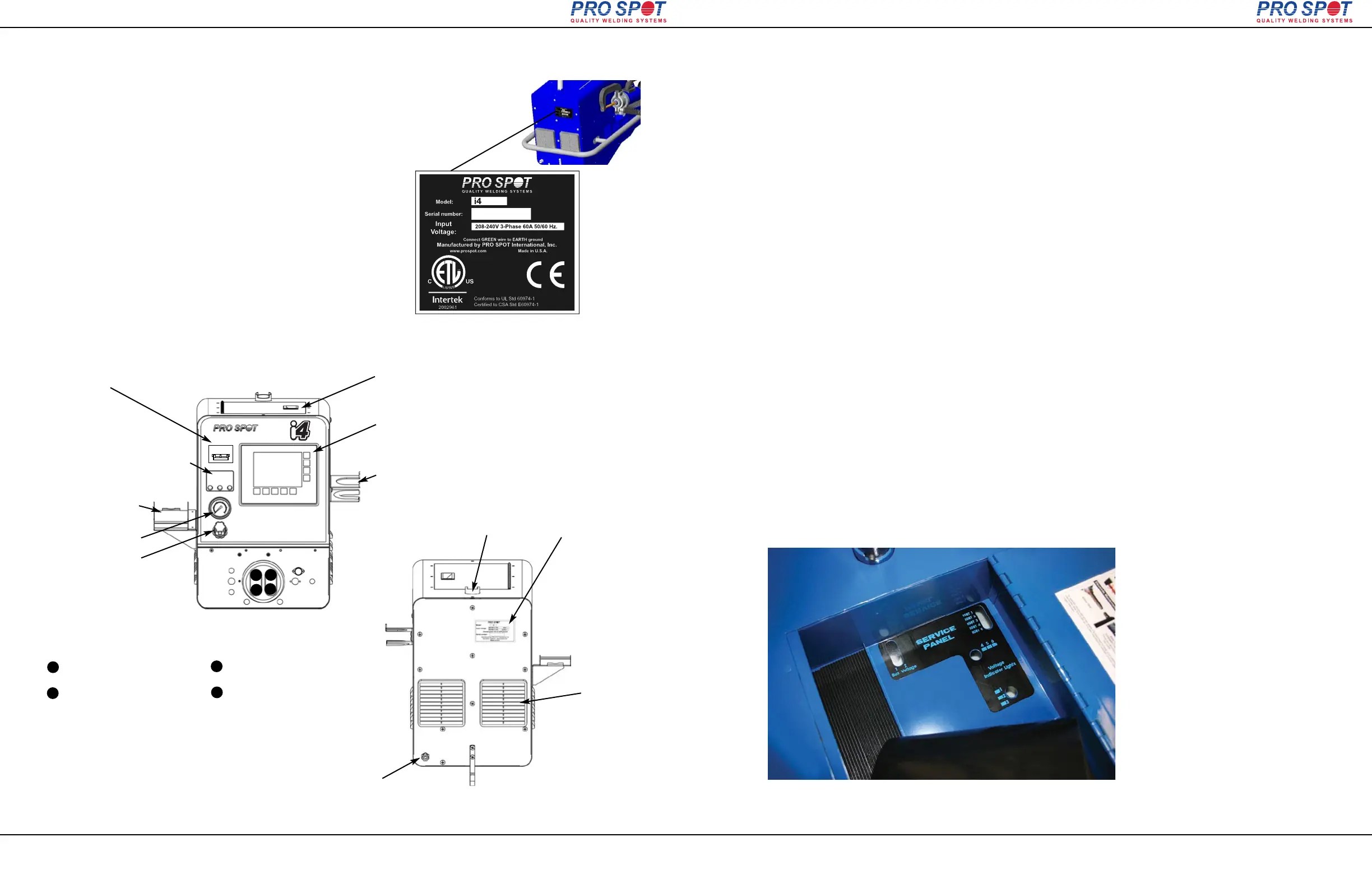
Air Pressure Regulator
Display Screen
Power Switch
Input Voltage Phase Indicator LED
Lights should illuminate when
Power switch on front panel is "ON"
(2 lights for 1 phase or 3 lights for 3
phase)
Cable Holder Bracket
Name Plate shows:
Input voltage,
Serial number, etc.
Cooling Fan
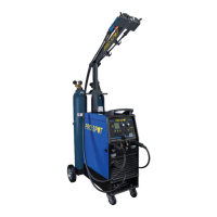
Air Input
Connect filtered air
100 PSI 7 BAR (min)
1
2
3
Single-Sided ground cable
Two-Sided spot gun cable
Single-Sided Weld Gun cable
Two-Sided ground cable
WELD CABLES CONFIGURATION
4
The name plate is at the rear of the welder unit.
The required voltage is indicated on the label.
Welding output is rated at 15V.
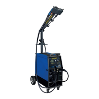
Figure 4.1 i4-Front View
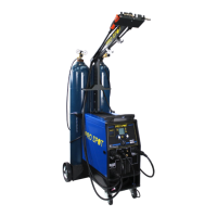
Figure 4.2 i4-Back View
Page 11
4.2.2 Getting familiar with your welder
4.2.1 Welder Overview & Technical Specifications
4.2 About your welder
Air Pressure Gauge
1
2
4
3
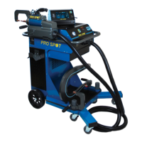
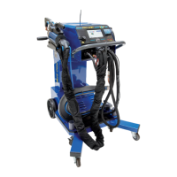
Two Sided Gun Holder
Single Sided Gun Holder
Tool Storage Tray
Cable Holder
i4
90021
All Info Copyright © Pro Spot International Inc.
4 Operation
Page 12
4.2.5 Service Panel Window – Control System Status Lamps
i4
Location: Inside the i4 and PR-2000 tool & accessory tray (under the rubber mat).
Purpose: To quickly determine the status of many internal systems without opening the
welder. The welder needs to be powered up. Look down through the window. There
are several lights to watch for. The Voltage Indicator windows have three LED lights in
each window, while the IGBT and Bus Bar windows have only one light per window.
NOTE: D means diode while the number determines the device’s board location.
1) Buss High Voltage OK: LED1 & 2 indicate 300 volts DC present. Both stay ON (but
often only one of them is seen unless top cover is removed).
D06= present
D26= present.
2) IGBT Control System OK: LEDs 1, 2, 3, 4 indicate voltage present across each
IGBT gate. Each LED should stay ON. LED 5 (yellow) indicates 15VDC control voltage
and should stay ON. These diodes are on a separate, vertically-mounted mini-board.
D107 = present
D108 = present
D109 = present
D110 = present
D101= 15V present
3) AC Input - Voltage Drop Condition: LEDs 4, 5, 6 indicate a problem if any of them
comes ON during welding. They all come on briefly during startup then stay OFF.
D23= Primary voltage drop 10%,
D22= Primary voltage drop 15%
D21= Primary voltage drop 20%
4) DC Voltage Indicators, LED 1, 2, 3 indicate logic voltages generated and present.
They come ON during startup and stay ON.
D10= 15V present
D11= 18V present
D12 = 24V present
Service Panel Window –
Control System Status Lamps
Tool tray mat removal required to view Service Panel Window.