ProfiHub B5+ / B5+RD User Manual
_______________________________________________
Version 2.0 – July 2014 Page 19 / 56
ProfiHub-B5-Plus-Manual-EN.docx © PROCENTEC 2014 - Copyright - all rights reserved
Note: Connecting the Indirect cable shielding is not required when the ground clips are used.
Testing
- If the Main-Channel recognizes valid PROFIBUS messages from one or more connected devices,
the RX-OK LED of the Main Channel should be blinking.
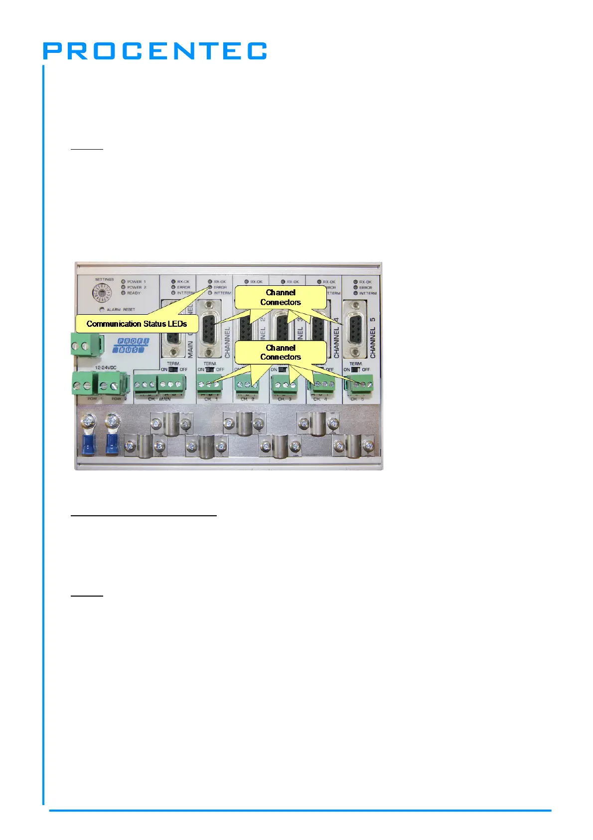
2.8 Spur Segments
Connect the spur segments to the connectors of Channel 1 to 5 (
Fig. 14
). The second method is to
place a PROFIBUS standardized plug on the DB9 connector of the specific Channel.
Pin layout of the screw terminals:
Pin “A”: Green wire
Pin “B”: Red wire
Pin “I”: Indirect cable shielding
Note: Connecting the Indirect cable shielding is not required when the ground clips are used.
Testing
- If a Channel recognizes valid PROFIBUS messages from one or more connected devices, the RX-
OK LED of the Channel should be blinking.
According to UL60950-1, if a copper PROFIBUS cable is used outside, it is required to install surge
protection that is suitable for PROFIBUS.
Fig. 14 - PROFIBUS DP spur connectors