4.3. Indicator Element (LED)
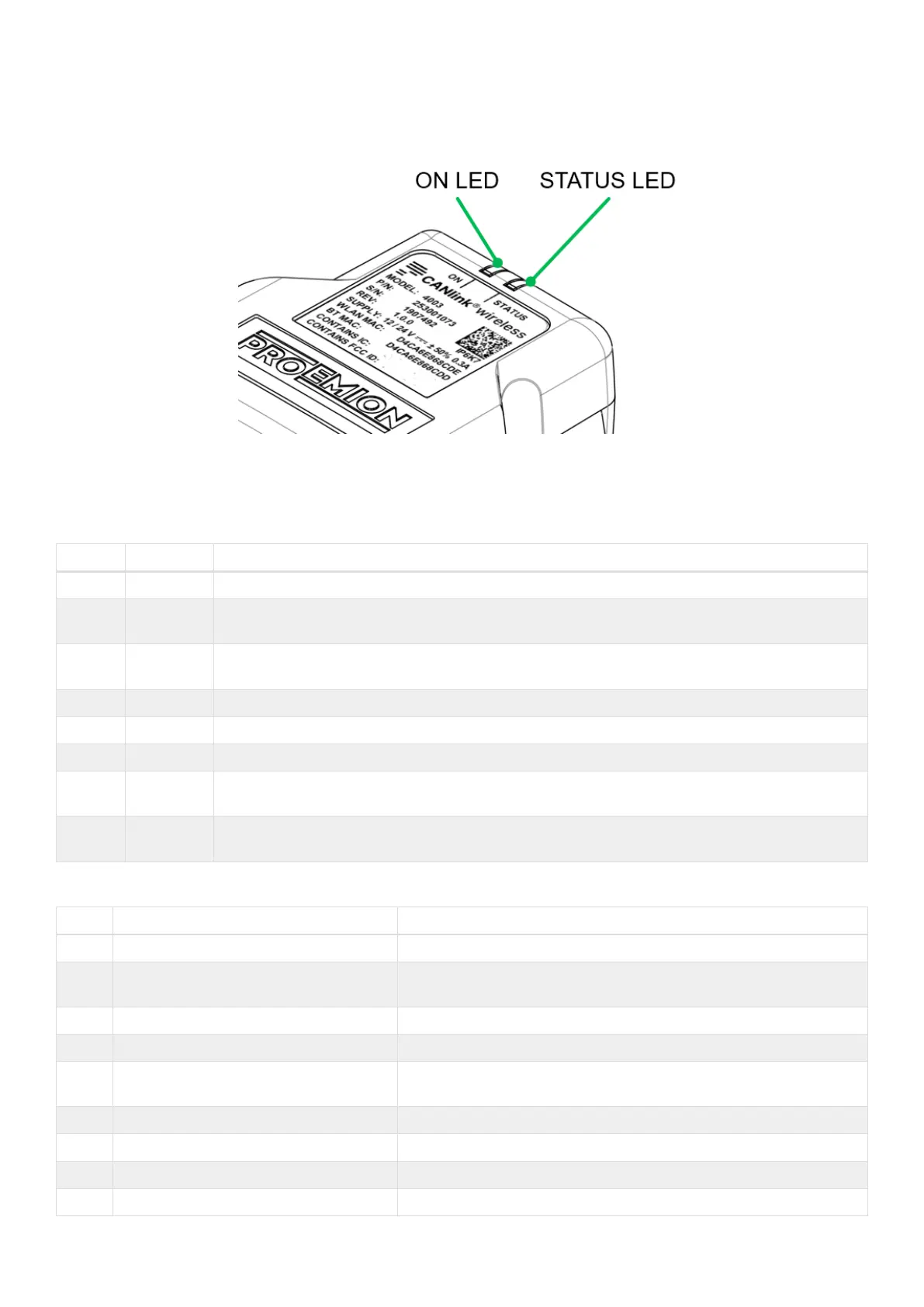
The front of the device features two RGB LEDs for indicating function and status.
Figure 12. LEDs
The following table shows possible LED states:
Table 14. ON LED
Color Status Meaning
- Off Device is switched off or in sleep mode.
Green Slow
Blinking
Device is in update mode and ready to receive an application firmware. The STATUS LED is
blinking in parallel.
Green Fast
Blinking
Firmware flashing process. The STATUS LED is blinking in parallel.
Green On Device switched on, terminal 30 voltage in permitted range (>= 6 and < 36 V)
Red On Device is switched on, terminal 30 voltage outside permitted range (< 6 or >= 36 V).
Orange On Device is in factory reset mode (STATUS LED is also orange in parallel).
Turquois
e
On Device is in Radio Module Update Mode (via HTTP Server) (STATUS LED is also turquoise in
parallel).
Pink On Active connection with CANlink wireless configurator. The STATUS LED is also pink in
parallel.
Table 15. STATUS LED
Color Status Meaning
- Off Device is switched off or in sleep mode.
Green Double Flash (200 ms on, 200 ms off,
200 ms on, 1000 ms off)
Initialization of the Device.
Green Blinking (200 ms on, 200 ms off) Device is ready for connection.
Green On Device is connected to a peer. There is no error.
Green Slow Blinking Device is in update mode and ready to receive an application
firmware. The ON LED is blinking in parallel.
Green Fast Blinking Firmware flashing process. The STATUS LED is blinking in parallel.
Green On Device is connected to a peer. There is no error.
Blue Blinking Data transfer active.
Blue On There is an wireless connection error.
CANlink wireless 4000 Device Manual
 Loading...