5.4.5. Mounting
Below you will find instructions on how to mount the device.
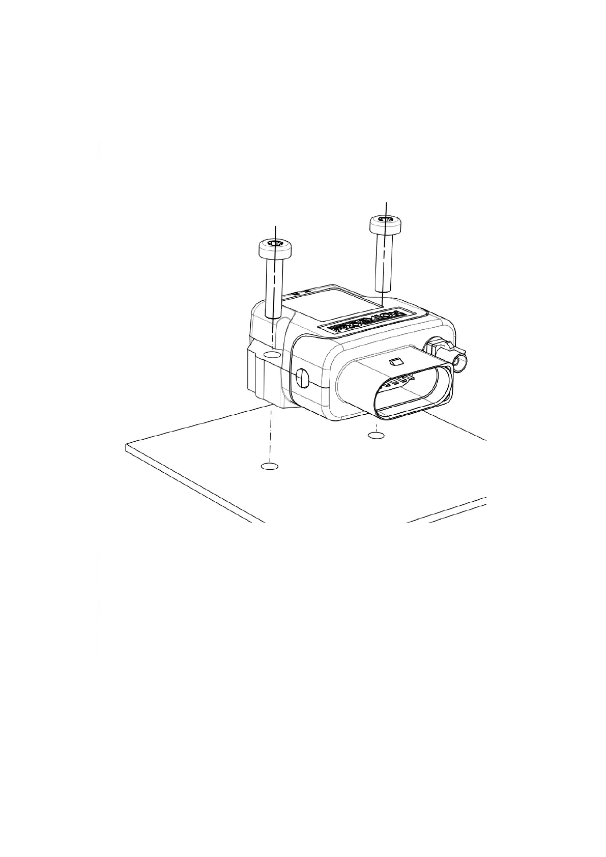
Directly affix the device with two flat headed screw ISO 14583 M6X30 TX which are at least 30 mm long. Tighten the
bolts with a torque of 3,4 Nm +/- 10%. In order to secure the bolts, we recommend using two hexagon nuts M6 self-
locking.
The mounting material is not included in the scope of supply.
To get the distance of the mounting holes, please refer to chapter Technical Drawings.
Figure 35. Direct bolt fastening
The Pressure compensation element at the bottom as shown in Device Elements must not be
exposed to direct jet water.
The recommended tightening torque for assembly is 3,4 Nm +/- 10%.
The outer diameter of the head for the fixing screws must be below 12.5 mm.
6. Operation
This chapter contains information on operating the device and the CANlink wireless configurator software.
6.1. CANlink wireless configurator
Configure the device with the CANlink wireless configurator software. To modify the configuration of your device, first
connect it to the PC. See chapter Connection with a PC via Bluetooth.
CANlink wireless 4000 Device Manual