4.2. Connectors
The device is equipped with the following connectors:
• 1x main plug connector, code 1 (14-pin) : CAN1 / CAN2 / VCC / GND / AIN1-2 / DOUT
• 1x RF antenna connector - FAKRA, code I (male)
NOTICE
According to the manufacturer’s information, the connectors are equipped for the following
minimum number of mating cycles:
Main plug connector: 10 cycles
Fakra plug: 100 cycles
If the minimum number of mating cycles is exceeded, individual parameters could lie outside
those in the specification.
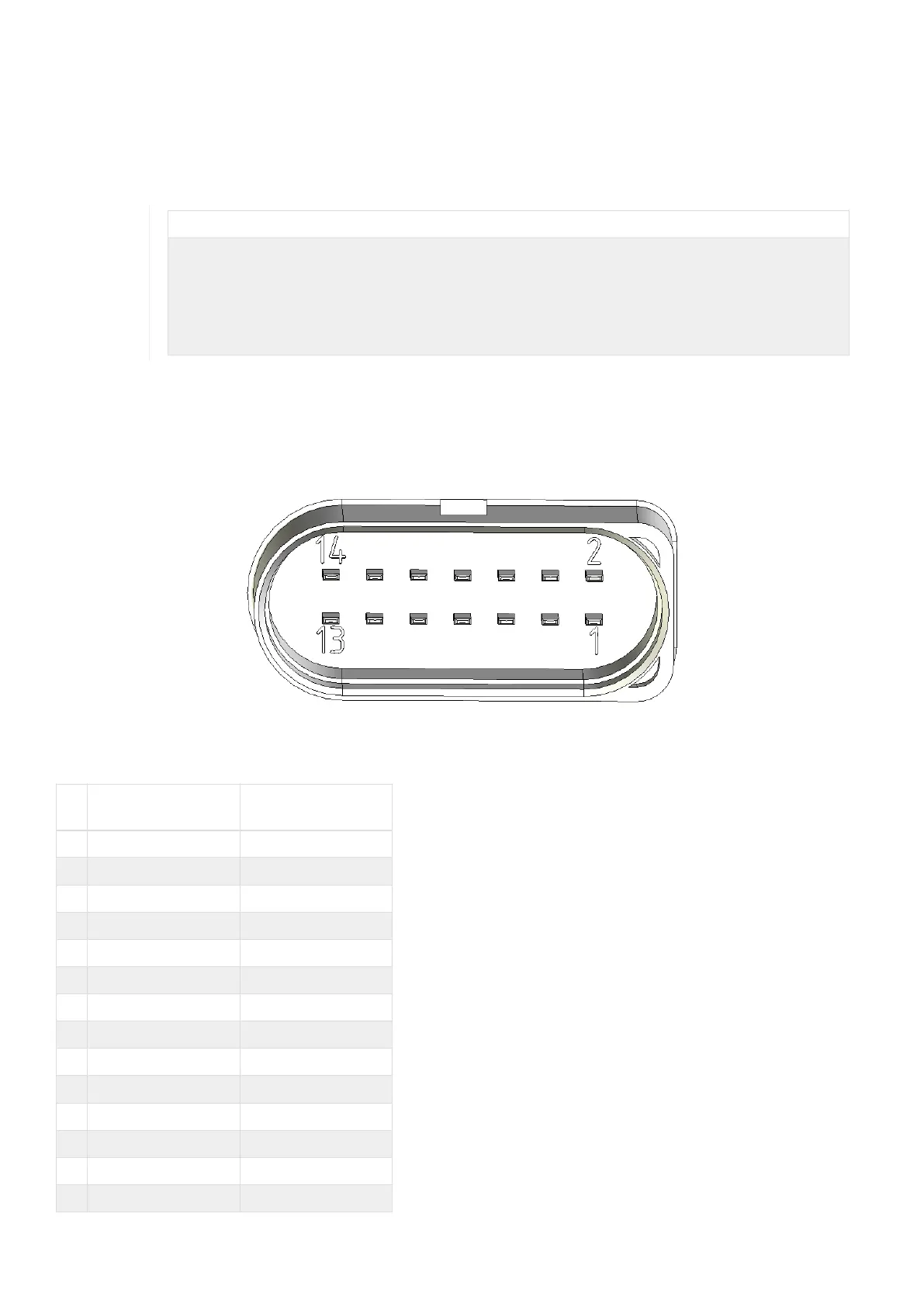
4.2.1. Main plug connector
Use the main plug connector to connect the device to the CAN bus and supply it with power. For the pin assignment of
the main plug connector, see the following overview.
Figure 6. Main plug connector
Table 12. Pin layout of main plug connector
Pi
n
Designation Description
1 Terminal 30 / VCC Power supply
2 Factory setting 1 Input
3 Terminal 31 / ground Power supply
4 Analog input 1 I/O input
5 Analog input 2 I/O input
6 Not used -
7 Digital output I/O output
8 Terminal 15 Input (ignition signal)
9 Factory setting 2 Input
10 Terminal 31 / ground Power supply
11 CAN2-High CAN, bidirectional
12 CAN2-Low CAN, bidirectional
13 CAN1-High CAN, bidirectional
14 CAN1-Low CAN, bidirectional
CANlink wireless 4000 Device Manual
 Loading...