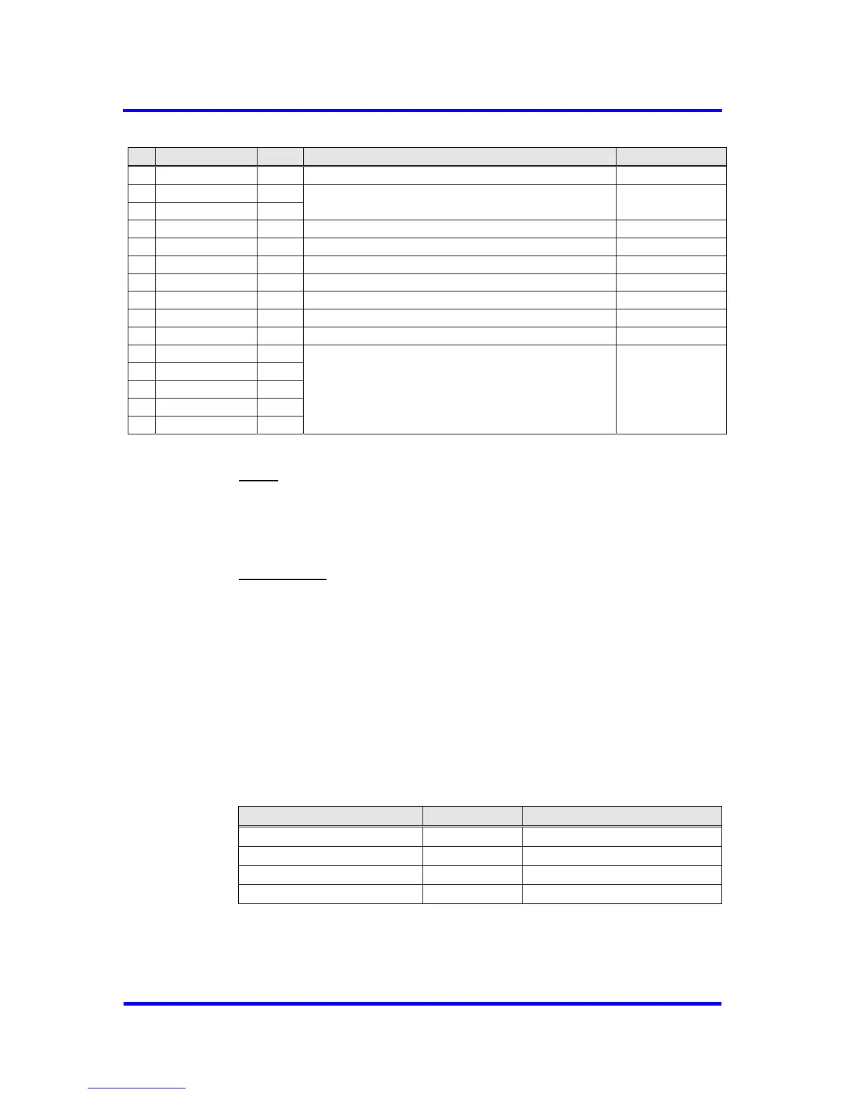
3 Pin Description
Pin Signal Name In/Out Description Source / Destination
30 RXD I(C) Serial Receive Port PROFIBUS Interface
31 AB7 I(C)
32 AB6 I(C)
Address Bus CPU, Memory
33 XCTS I(C) Clear to Send: ‘0’ = send enable FSK Modem
34 XTEST0 I(C) Pin must be connected to VDD.
35 XTEST1 I(C) Pin must be connected to VDD.
36 RESET I(CS) Connect Reset Input with CPU’s port pin.
37 AB4 I(C) Address Bus CPU, Memory
38 VSS
39 VDD
40 AB3 I(C)
41 AB2 I(C)
42 AB5 I(C)
43 AB1 I(C)
44 AB0 I(C)
Address Bus CPU, Memory
Figure 3-1: Pin Assignment
Notes: All signals that begin with X.. are LOW active.
C32-Mode means ‘Synchronous Intel Mode’ and
C165-Mode means ‘Asynchronous Intel Mode’.
VDD = +5 V
VSS = 0 V
Input Levels:
I ( C ) : CMOS
I ( CS ) : CMOS, Schmitt-Trigger
I (CPD ) : CMOS, pulldown
I (TS ) : TTL, Schmitt-Trigger
4K Byte RAM extension
Beginning with Step B of the VPC3+ the communication RAM has been
extended to 4K Byte, whereas Step A only has 2K Byte. To access the
entire 4K Byte RAM in VPC3+C an additional address signal AB11 is
required. Which pin is assigned to A11 depends on the Processor Interface
Mode used (see Figure 3-2). Due to compatibility reasons the pin which is
now assigned to A11 was unused in Step A for the certain Interface Mode.
Processor Interface Mode Pin Signal Name
Synchronous Intel Mode 1 XCS
Asynchronous Intel Mode 24 ALE/AS
Asynchronous Motorola Mode 2 XWR/E_CLOCK
Synchronous Motorola Mode 24 ALE/AS
Figure 3-2 : Pin assignment for AB11
The 4K Byte RAM extension must be enabled in Mode Register 2 (see
section 5.1.3). By default the 4K Byte mode is disabled.
10 Revision 1.03
VPC3+C
User Manual
Copyright © profichip GmbH 2004-2006