PROFIBUS Interface 9
9 PROFIBUS Interface
the
terface drivers.
9.1 Pin Assignment
The data transmission is performed in RS485 operating mode (i.e., physical
S485). The VPC3+C is connected via the following signals to R
galvanically isolated in
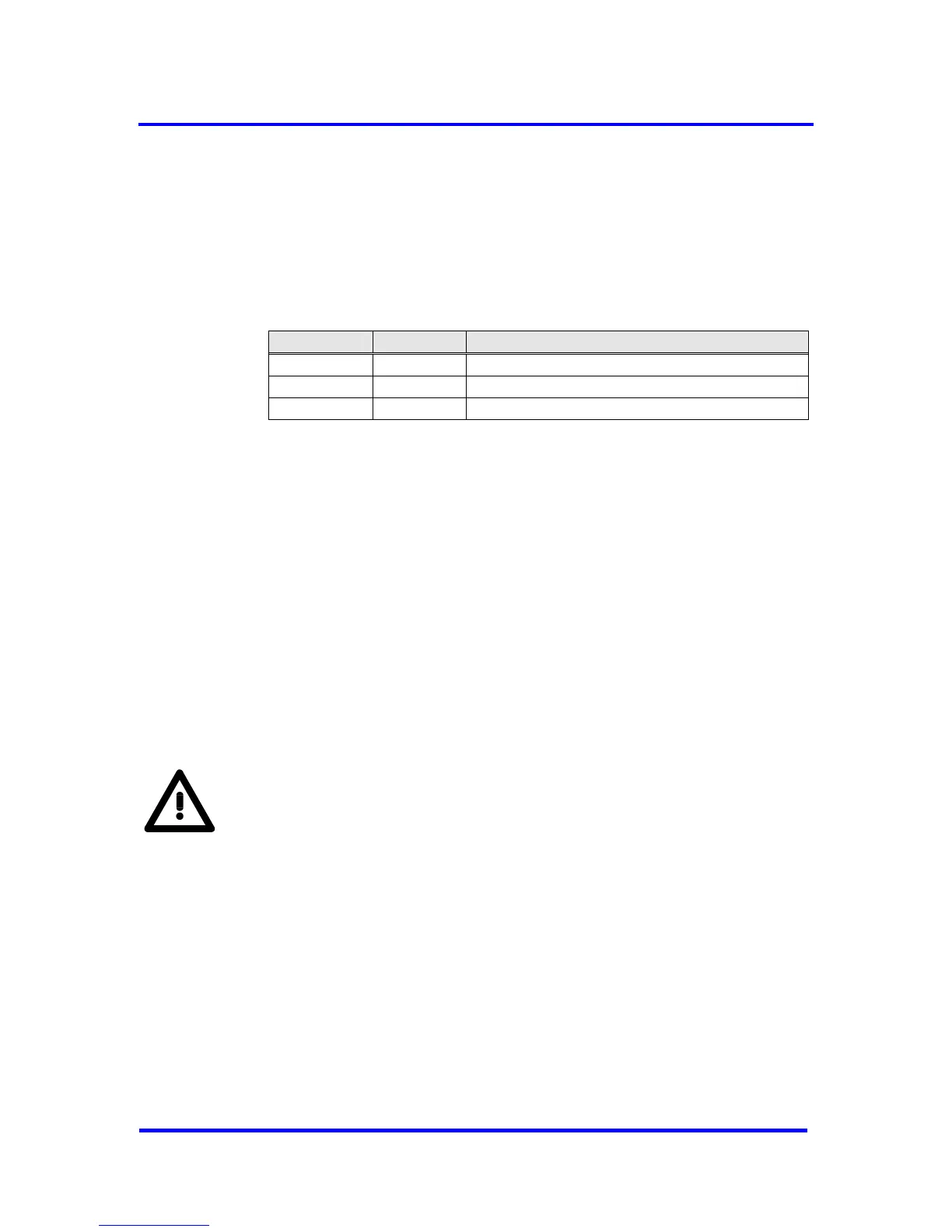
Signal Name Input/Output Function
RTS Output Request to send
TXD Output Sending data
RXD Input Receiving data
Figure 9-1: PROFIBUS Signals
The PROFIBUS interface is a 9-way, sub D, plug connector with the
following pin assignment.
Pin 1 - Free
Pin 2 - Free
Pin 3 - B line
Pin 4 - Request to send (RTS)
Pin 5 - Ground 5V (M 5 )
Pin 6 - Potential 5V (floating P5 )
Pin 7 - Free
Pin 8 - A line
Pin 9 - Free
The cable shield must be connected to the plug connector housing.
The free pins are described as optional in IEC 61158-2.
CAUTION:
The pin names A and B on the plug connector refer to the signal names in
the RS485 standard and not the pin names of driver ICs.
Keep the wires from driver to connector as short as possible.
VPC3+C User Manual
Revision 1.03 79
Copyright © profichip GmbH 2004-2006