8 Hardware Interface
8.3 UART
nverts the parallel data structure into a serial data flow.
-Send (RTS) is generated before the first character. The
fter each character.
he receiver converts the serial data flow into the parallel data structure
e l he four-fold transmission speed. Stop
s ('Dis_Stop_Control = 1' in
ter 0 or Set_P r DP). One requirement of the
is tha tates are permitted between the
The transmitter ensures that this
he synchronization of the receiver starts with the falling edge of the start
nd the stop bit are also scanned in the middle of
e bit-time. To compensate for the synchronization error, a repeater gen-
ion of the stop bit at a four-fold scan rate. In this case
ould be parameterized with 'Dis_Start_Control = 1' (in Mode
et_Prm telegram for DP) in order to increase the permissible
8.4 ASIC T
and I/O pins can be switched to the high-resistance state via
test pin. An additional XTEST1 input is provided to test the
The transmitter co
Signal Request-to
XCTS input is available for connecting a modem. After RTS active, the
transmitter must hold back the first telegram character until the modem acti-
vates XCTS. XCTS is checked again a
T
and scans th serial data f ow with t
bit testing can be switched off for test purpose
Mode Regis rm telegram fo
PROFIBUS protocol t no rest s
telegram characters. VPC3+C
specification is maintained.
T
bit. The start bit is checked again in the middle of the bit-time for low level.
The data bits, the parity a
th
erates a ±25% distort
the VPC3+ sh
Register 0 or S
distortion of the stop bit.
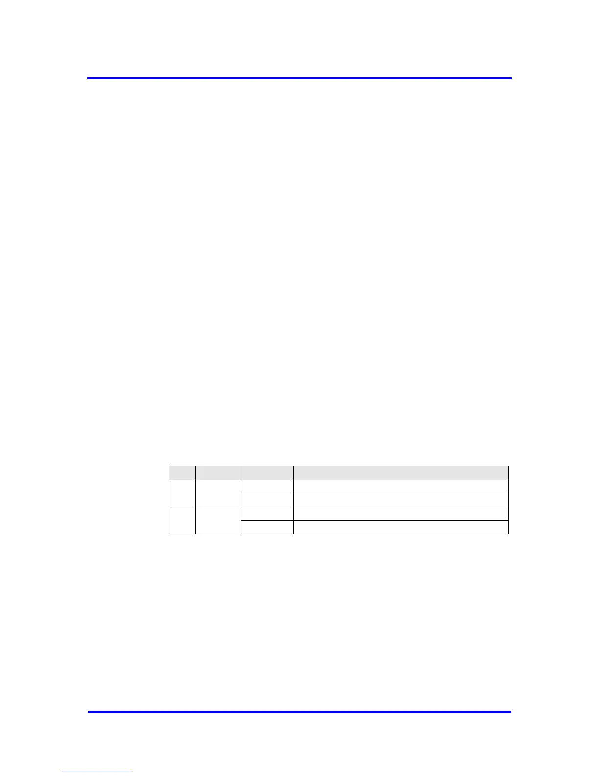
est
All output pin
the XTEST0
s
chip on automatic test devices (not in the target hardware environment!).
Pin Name Value Function
VSS (GND) All outputs high-resistance
34 XTEST0
VDD Normal VPC3+ function
VSS (GND) Various test modes
35 XTEST1
VDD Normal VPC3+ function
Figure 8-11: Test Ports
78 Revision 1.03
VPC3+C
User Manual
Copyright © profichip GmbH 2004-2006