ASIC Interface 5
5 ASIC Interface
5.1 Mode Registers
In the VPC3+C parameter bits that access the controller directly or which
the controller directly sets are combined in three Mode Registers (0, 1 and
2).
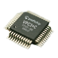
5.1.1 Mode Register 0
Setting parameters for Mode Register 0 may take place in the Offline
state only (for example, after power-on). The VPC3+C may not exit the
Offline state until Mode Register 0, all Control and Organizational Pa-
rameters are loaded (START_VPC3 = 1 in Mode Register 1).
Bit Position
Address
7 6 5 4 3 2 1 0
Designation
06H
(Intel)
Freeze_
Supported
Sync_
Supported
Early_Rdy
Int_Pol
minT
SDR
WD_Base
Dis_Stop_
Control
Dis_Start_
Control
Mode Reg 0
7 .. 0
See below for
coding
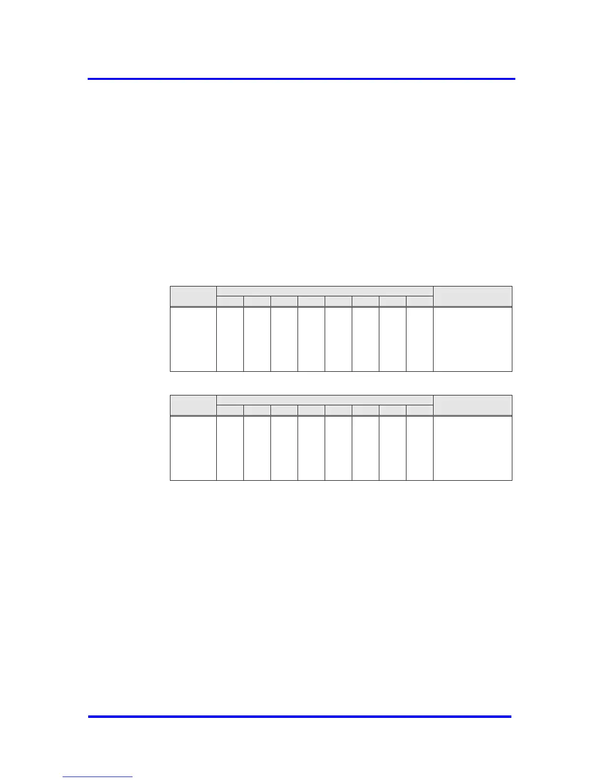
Bit Position
Address
15 14 13 12 11 10 9 8
Designation
07H
(Intel)
Reserved
PrmCmd_
Supported
Spec_Clear_
Mode *)
Spec_Prm_
Buf_Mode **)
Set_Ext_Prm
_Supported
User_Time_
Base
EOI_Time_
Base
DP_Mode
Mode Reg 0
15 .. 8
See below for
coding
*) If Spec_Clear_Mode = 1 (Fail Safe Mode) the VPC3+C will accept Data_Exchange
telegrams without any output data (data unit length = 0) in the state DATA-EXCH. The
reaction to the outputs can be parameterized in the parameterization telegram.
**) When a large number of parameters have to be transmitted from the DP-Master to the
DP-Slave, the Aux-Buffer 1/2 must have the same length as the Parameter-Buffer.
Sometimes this could reach the limit of the available memory in the VPC3+C. When
Spec_Prm_Buf_Mode = 1 the parameterization data are processed directly in this special
buffer and the Aux-Buffers can be held compact.
VPC3+C User Manual
Revision 1.03 19
Copyright © profichip GmbH 2004-2006