10 Operational Specifications
10.7 Timing Characteristics
10.7.1 System
lock
lock frequency is 48 MHz. Distortion of the clock signal is permissible up
to a ratio of 30:70 at the threshold levels 0.9 V and 2.1 V.
All signals beginning with ‘X’ are ‘low active’. All timing values are based on
the capacitive loads specified in the table above.
Bus Interface
C
C
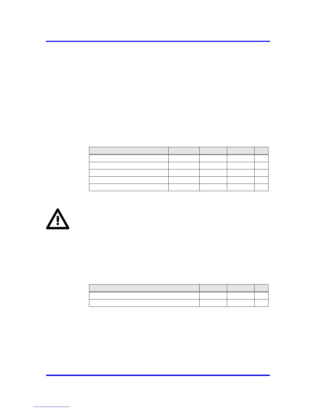
Parameter Symbol MIN MAX Unit
Clock period T 20.83 20.83
Clock high time T
CH
6.25 14.6 ns
Clock low time T
CL
6.25 14.6 ns
Clock rise time T
CR
4 ns
Clock fall time T
CF
4 ns
Figure 10-7: Clock Timing
Note:
For 3.3V operation the VPC3+C is equipped with 5V tolerant inputs except
for the clock pin CLK. When using 3.3V supply voltage the clock input needs
to be 3.3V level.
Interrupt:
After acknowledging an interrupt with EOI, the interrupt output of the
VPC3+C is deactivated for at least 1 us or 1 ms depending on the bit
EOI_Time_Base in Mode Register 0.
Parameter MIN MAX Unit
Interrupt inactive time EOI_Timebase = ‘0’ 1 1 µs
Interrupt inactive time EOI_Timebase = ‘1’ 1 1 ms
Figure 10-8: End-of-Interrupt Timing
Reset:
VPC3+C requires a minimum reset phase of 100 ns at power-on.
84 Revision 1.03
VPC3+C
User Manual
Copyright © profichip GmbH 2004-2006