Memory Organization 4
4 Memory Organization
4.1 Overview
The internal Control Parameters are located in the first 21 addresses. The
latches/registers either come from the internal controller or influence the
controller. Certain cells are read- or write-only. The internal working cells,
which are not accessible by the user, are located in RAM at the same
address locations.
The Organizational Parameters are located in RAM beginning with address
16H. The entire buffer structure (for the DP-SAPs) is based on these pa-
rameters. In addition, general parameter data (Station_Address,
Ident_Number, etc.) and status information (Global_Control command, etc.)
are also stored in these cells.
Corresponding to the parameter setting of the Organizational Parameters,
the user-generated buffers are located beginning with address 40H. All
buffers or lists must begin at segment addresses (8 bytes segmentation for
2K Byte mode, 16 bytes segmentation for 4K Byte mode).
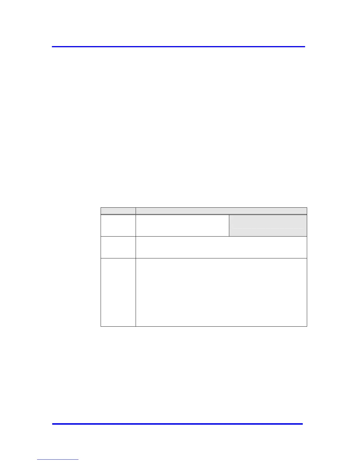
Address Function
000H
:
015H
Control Parameters
(latches/registers) (21 bytes)
Internal working cells
016H
:
03FH
Organizational Parameters (42 bytes)
040H
:
7FFH (FFFH)
DP-buffers: Data in (3)*
Data out (3)**
Diagnosis data(2)
Parameter data (1)
Configuration data (2)
Auxiliary buffers (2)
SSA-buffer (1)
DP-V1-buffer: SAP-List (1)
Indication / Response buffers ***
DP-V2-buffer: DXB out (3)****
DXB-buffers (2)
CS-buffers (1)
Figure 4-1: Memory Table
* Data in means input data from DP-Slave to DP-Master
** Data out means output data from DP-Master to DP-Slave
*** number of buffers depends on the entries in the SAP-List
**** DXB out means input data from another DP-Slave (slave-to-slave communication)
VPC3+C User Manual
Revision 1.03 13
Copyright © profichip GmbH 2004-2006