ddress-Buffer
Parameter-
Buffer
D-N changed
by VPC3+
N-U changed
by User
changed by User
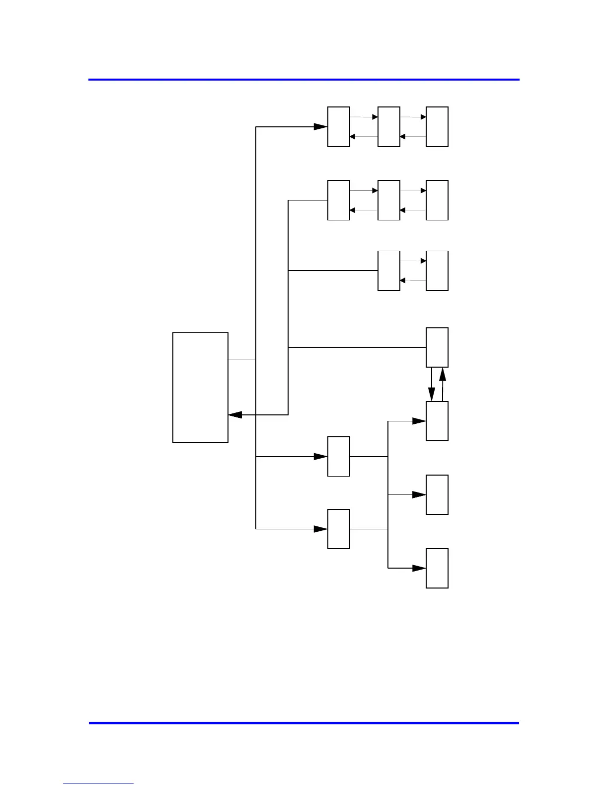
Figure 6-1: DP_SAP Buffer Structure
The VPC3+C first stores the parameter telegrams (Set_Slave_Add and
Set_(Ext_)Prm) and the configuration telegram (Chk_Cfg) in Aux-Buffer 1
or Aux-Buffer 2. If the telegrams are error-free, data is exchanged with the
corresponding target buffer (Set_Slave_Add-Buffer, Parameter-Buffer and
Config-Buffer). Each of the buffers to be exchanged must have the same
length. In the R_Aux_Buf_Sel parameter cell (see Figure 6-2) the user
defines which Aux_buffers are to be used for the telegrams mentioned
36 Revision 1.03
VPC3+C
User Manual
Copyright © profichip GmbH 2004-2006