6 PROFIBUS DP Interface
Parameter Data Processing Sequence
In the case of a positive validation of more than seven data bytes, the
VPC3+C carries out the following reaction:
The VPC3+C exchanges Aux-Buffer 1/2 (all data bytes are entered here)
for the Parameter-Buffer, stores the input data length in R_Len_Prm_Data
and triggers the New_Prm_Data interrupt. The user must then check the
User_Prm_Data and either reply with User_Prm_Data_Okay_Cmd or with
User_Prm_Data_Not_Okay_Cmd. The entire telegram is entered in this
buffer. The user parameter data are stored beginning with data byte 8, or
with byte 10 if DPV1_Status bytes used.
The user response (User_Prm_Data_Okay_Cmd or User_Prm_Data_-
Not_Okay_Cmd) clears the New_Prm_Data interrupt. The user cannot
acknowledge the New_Prm_Data interrupt in the IAR register.
With the User_Prm_Data_Not_Okay_Cmd message, relevant diagnosis
bits are set and the DP_SM branches to WAIT-PRM.
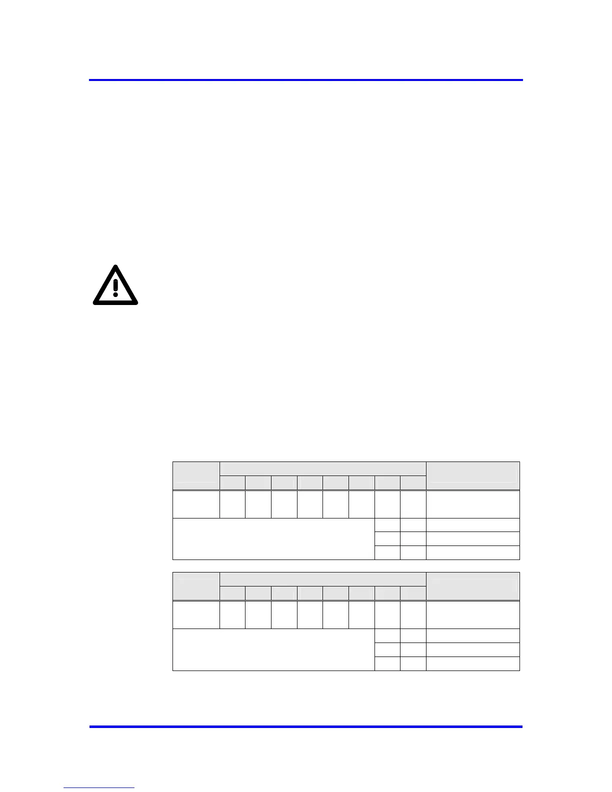
The User_Prm_Data_Okay and User_Prm_Data_Not_Okay acknowledge-
ments are read accesses to defined registers with the relevant signals:
• User_Prm_Finished:
No additional parameter telegram is present.
• Prm_Conflict:
An additional parameter telegram is present,
processing again
• Not_Allowed:
Access not permitted in the current bus state
Bit Position
Address
7 6 5 4 3 2 1 0
Designation
0EH 0 0 0 0 0 0
⇓ ⇓
User_Prm_
Data_Okay
0 0 User_Prm_Finished
0 1 Prm_Conflict
1 1 Not_Allowed
Bit Position
Address
7 6 5 4 3 2 1 0
Designation
0FH 0 0 0 0 0 0
⇓ ⇓
User_Prm_
Data_Not_Okay
0 0 User_Prm_Finished
0 1 Prm_Conflict
1 1 Not_Allowed
Figure 6-7: Coding of User_Prm_(Not)_Okay_Cmd
42 Revision 1.03
VPC3+C
User Manual
Copyright © profichip GmbH 2004-2006