7 PROFIBUS DP Extensions
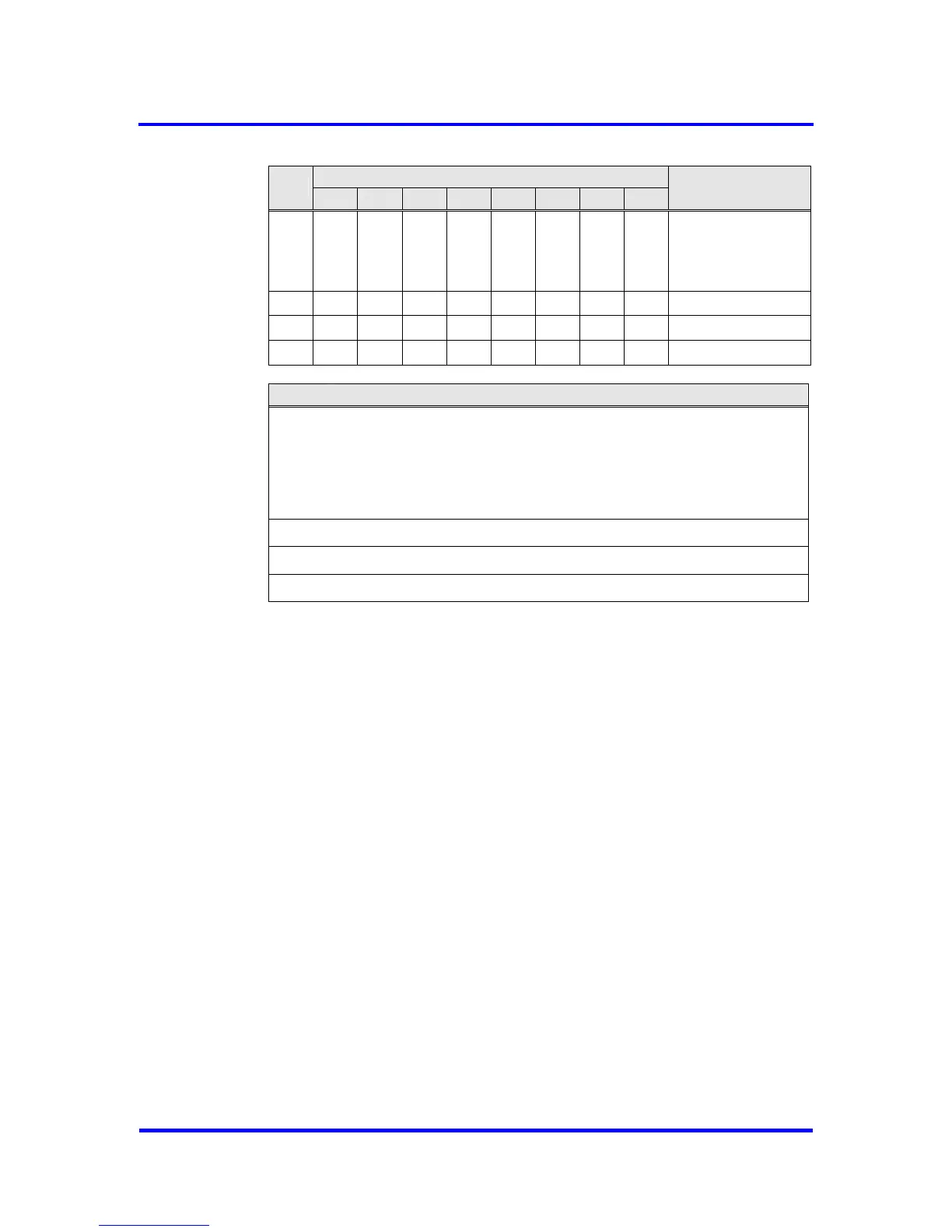
Bit Position
Byte
7 6 5 4 3 2 1 0
Designation
0
USER
IND
RESP
INUSE
Control
1 Max_Length
2 Length
3 Function Code
SAP-List entry:
Byte 0
Control: bits for buffer management
USER buffer assigned to user
IND indication data included in buffer
RESP response data included in buffer
INUSE buffer assigned to VPC3+C
Byte 1
Max_Length: length of buffer
Byte 2
Length: length of data included in buffer
Byte 3
Function Code: function code of the telegram
Figure 7-4: Buffer Header
Processing Sequence
A received telegram is compared with the values in the SAP-List. If this
check is positive, the telegram is stored in an Indication-Buffer with the
INUSE bit set. In case of any deviations the VPC3+C responses with “no
service activated” (RS) or if no free buffer is available with “no resource”
(RR). After finishing the processing of the incoming telegram, the INUSE bit
is reset and the bits USER and IND are set by VPC3+C. Now the FDL_Ind
interrupt is generated. Polling telegrams do not produce interrupts. The
RESP bit indicates response data, provided by the user in the Response-
Buffer. The Poll_End_Ind interrupt is set after the Response-Buffer is sent.
Also bits RESP and USER are cleared.
56 Revision 1.03
VPC3+C
User Manual
Copyright © profichip GmbH 2004-2006