PROFIBUS DP Extensions 7
DP-Slave in a IsoM network
To enable cyclic synchronization via the ‘Simple Sync Mode', the bit
DX_Int_Port in Mode Register 2 have to be set. Bit SYNC_Ena must not be
set. The settings of the pulse polarity are adjusted like described in the
IsoM.
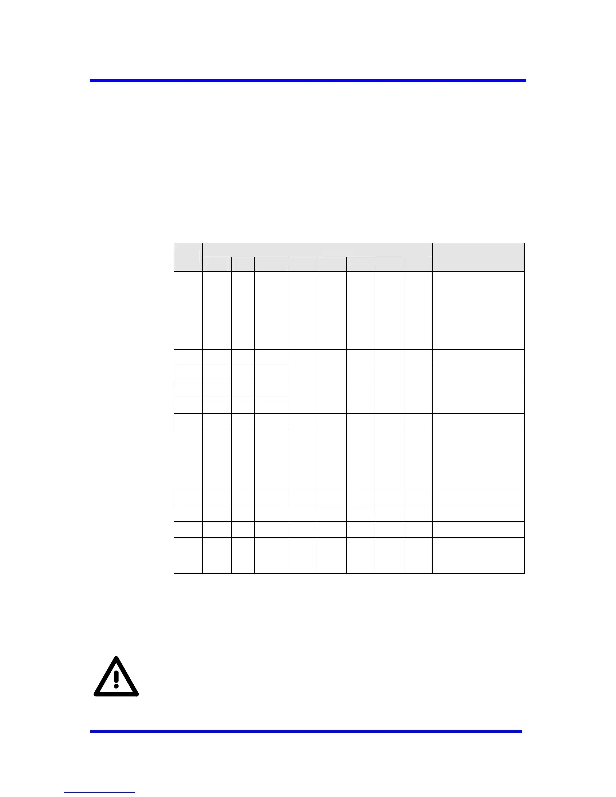
For the parameterization telegram the DP format is used. Though the
DPV1_Status bytes 1-3 could be used as User_Prm_Data, it is generally
recommended starting the User_Prm_Data at byte 10.
Bit Position
Byte
7 6 5 4 3 2 1 0
Designation
0
Sync_Req =
depends on
SYNCH-format
Freeze_Req =
depends on
SYNCH-format
Station_Status
1 WD_Fact_1
2 WD_Fact_2
3 minT
SDR
4 Ident_Number_High
5 Ident_Number_Low
6
Group_8 = 1
Group_Ident
7 DPV1_Status_1
8 DPV1_Status_2
9 DPV1_Status_3
10
:
246
User_Prm_Data
Figure 7-19: Format of Set_Prm for DP-Slave using isochrones cycles
In opposite to IsoM the DX_Out interrupt is generated first after the receipt
of a SYNCH telegram. If no Data_Exchange telegram had been received
before a SYNCH occurred, no synchronization signal is generated.
For this mechanism the interrupt controller ist used. Hence no signal
will be generated, if the mask for DX_Out in the IMR is set. Since the
synchronization signal is now the DX_Out interrupt, it remains until
the interrupt acknowledge.
VPC3+C User Manual
Revision 1.03 67
Copyright © profichip GmbH 2004-2006